Philips Semiconductors
TDA1562Q application note
Koninklijke Philips Electronics N.V.
Application note Rev. 01.02 — 05 May 2006 46 of 62
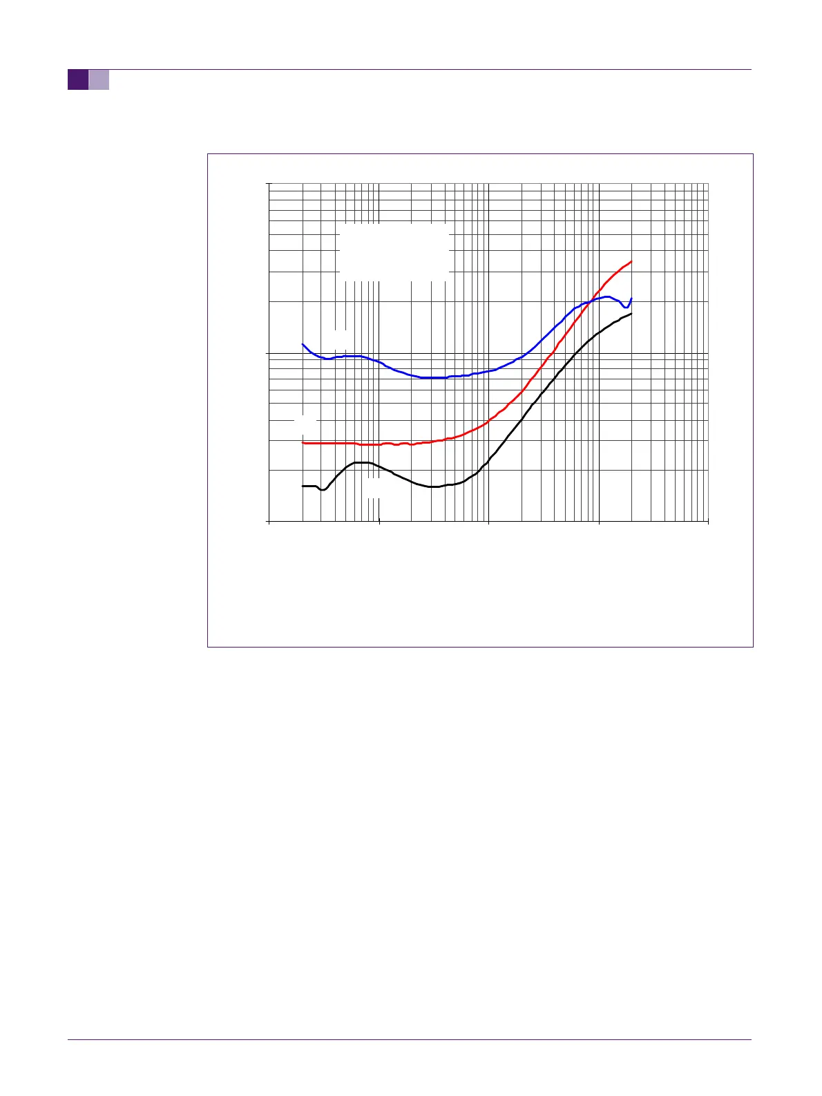
A: Po=1W
B: Po=10W
C: Po=40W
Fig 34. THD vs. frequency at constant output power
At a constant output power of 1W the TDA1562 behaves like any class AB BTL
amplifier. The THD (+noise) increases with the signal frequency as a result of crossover
distortion.
Below 10W, most of the THD+noise figures are caused by noise and crossover
distortion. Since these are constant numbers, the THD+noise ratio decreases as the
output power increases.
Above 10W, artifacts from the lifter circuitry are responsible for increased THD numbers.
THD vs Freq
0.01
0.1
1
0.01 0.1 1 10 100
F(kHz)
THD(%)
Vp=14.4V
Rl=4ohms
Clift=8200uF/16V
A
C
B