Mounting and installation
108997_en_04 PHOENIX CONTACT 37 / 226
3.5.3 Mounting and removing the devices
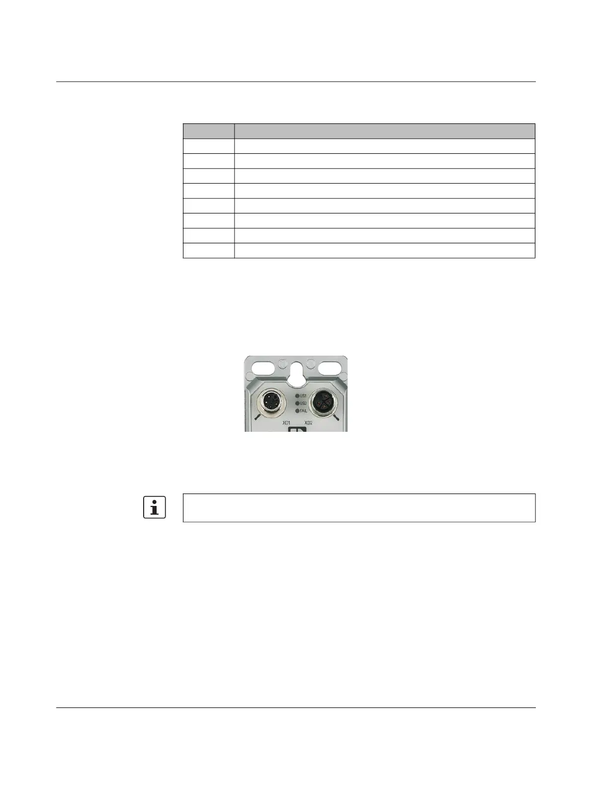
Use the drilling holes to screw the device directly to a level surface or to a profile. Do not use
this device to bridge gaps, in order to prevent forces being transmitted via the device.
For drill hole spacing, refer to Figure 322.
Figure 324 Drill holes
For mounting, use M5 or M6 screws with a head diameter larger than 7 mm and up to
10.3 mm, maximum. When using M4 screws, you have to use washers. The use of Schnorr
safety washers in accordance with DIN 6798 is possible.
Table 3-12 Key for FL SWITCH 26xx/27xx
Number Meaning
1 Connection of the supply voltage (power in)
2 Smart mode button (underneath the metal cap)
3 Slot for optional microSD card (underneath the metal cap)
4 Diagnostic and status indicators
5 Marking field
6 PROFINET status LEDs (for PN versions only)
7 M12 Ethernet ports
8 Power out
Observe the maximum torque of the screws.
 Loading...