onlinecomponents.com
IBSL SYS PRO UM E
1-38 6057AC01
• Measure the polarity of the wires you want to connect with the
BK module or determine the polarity through testing. The U
SL
LED
lights up if everything is connected correctly.
• Connect the last module (B in Figure 1-31) to the BK module (IN). The
devices flash at 0.5 Hz.
• Connect the first module (A in Figure 1-31) to the BK module (OUT).
The devices flash at 0.5 Hz.
If the cables are not polarized correctly, the installation local bus is not
ready for operation.
If this functionality is not ensured for some special function modules, this is
stated in the corresponding data sheet.
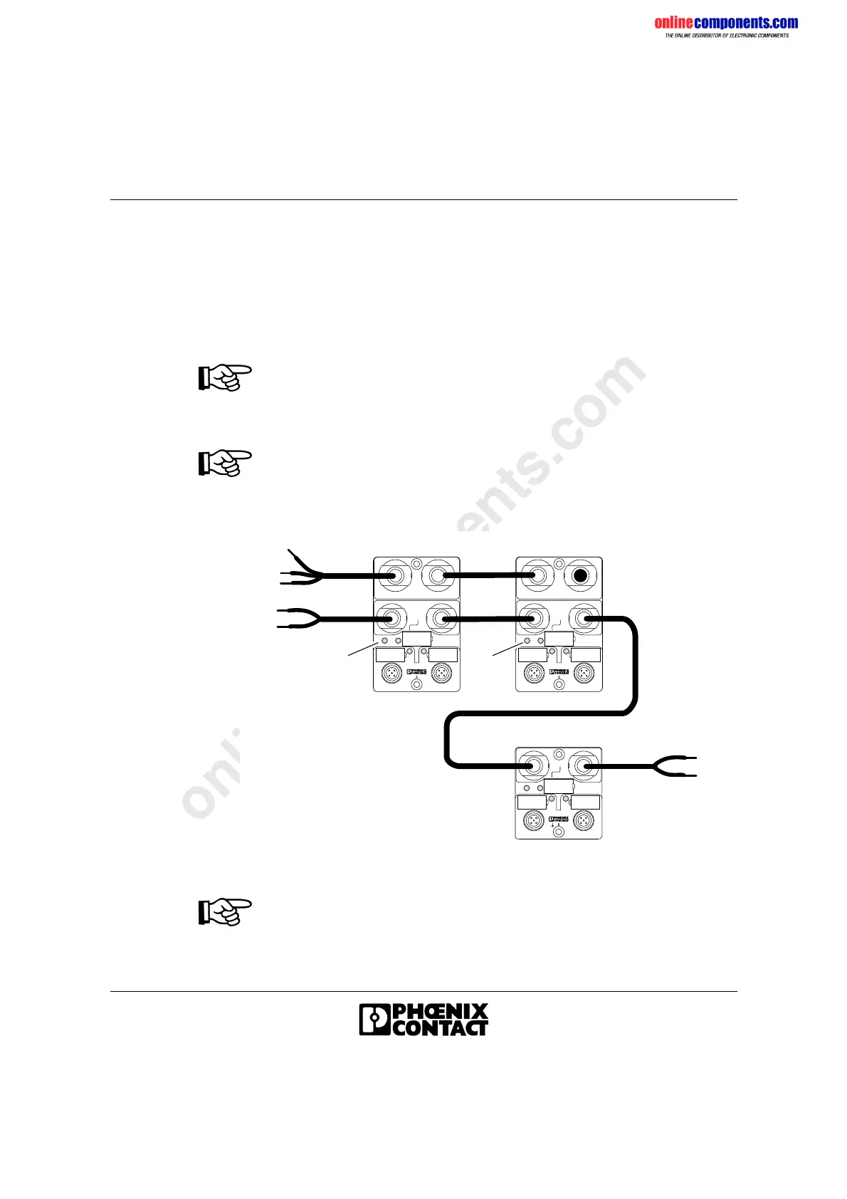
For the actuator supply, a separate power supply unit must be used to
avoid effects on the INTERBUS system.
• Apply the I/O voltage U
S
to the output modules. The LED US on the
modules must be on.
Figure 1-32 Actuator supply connection
If an actuator supply voltage U
S
is not applied, no error message is
generated. If the actuator supply voltage is not applied, the DIAG LED does
not indicate an error.
IBSL BOX 24 DO 2/2 M12-2AIBSL BOX 24 DO 2/2 M12-2A
IBSL BOX 24 DI 2/2 M12
IN
OUT
IN
OUT
IN
OUT
24V
IN
OUT
IN
OUT
24V
IN
OUT
US
5109B708
US
U
S
 Loading...