onlinecomponents.com
IBSL SYS PRO UM E
1-20 6057AC01
1.8 Connecting INTERBUS
1.8.1 Connecting the Remote Bus (BK Module With
IP 20 Protection)
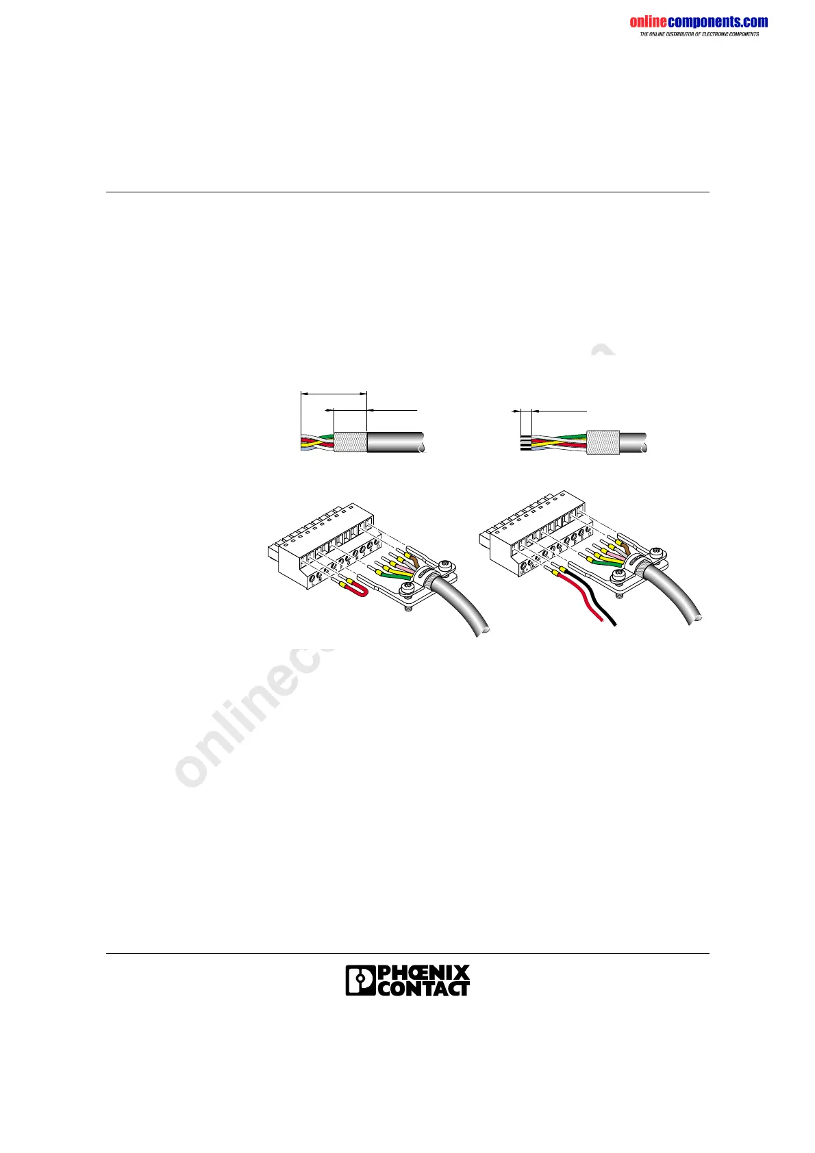
Fit the MINI-COMBICON male connectors that are also supplied to the
remote bus cable.
Figure 1-15 Assembling MINI-COMBICON male connectors
• Strip approx. 30 mm (1.181 in.) off the outer cable sheath (Figure 1-15,
A).
• Shorten the braided shield to 15 mm (0.591 in.) (Figure 1-15, A) and
place it around the outer cable sheath (Figure 1-15, B).
• Remove the protective foil.
• Cut off the white wire close to the outer cable sheath, as it is not
required.
• Strip approx. 5 mm (0.197 in.) off the wires (Figure 1-15, Fig. B).
• Crimp ferrules to the end of the wires (optional).
• Wire the Remote IN and Remote OUT connectors as shown below.
3 0 m m
( 1 . 1 8 1 " )
1 5 m m
( 0 . 5 9 1 " )
A
5 m m
( 0 . 1 9 7 " )
B
6 0 5 7 A 0 1 5
D
C
+
-
R e m o t e I N
R e m o t e O U T
 Loading...