onlinecomponents.com
INTERBUS Loop
6057AC01 1-21
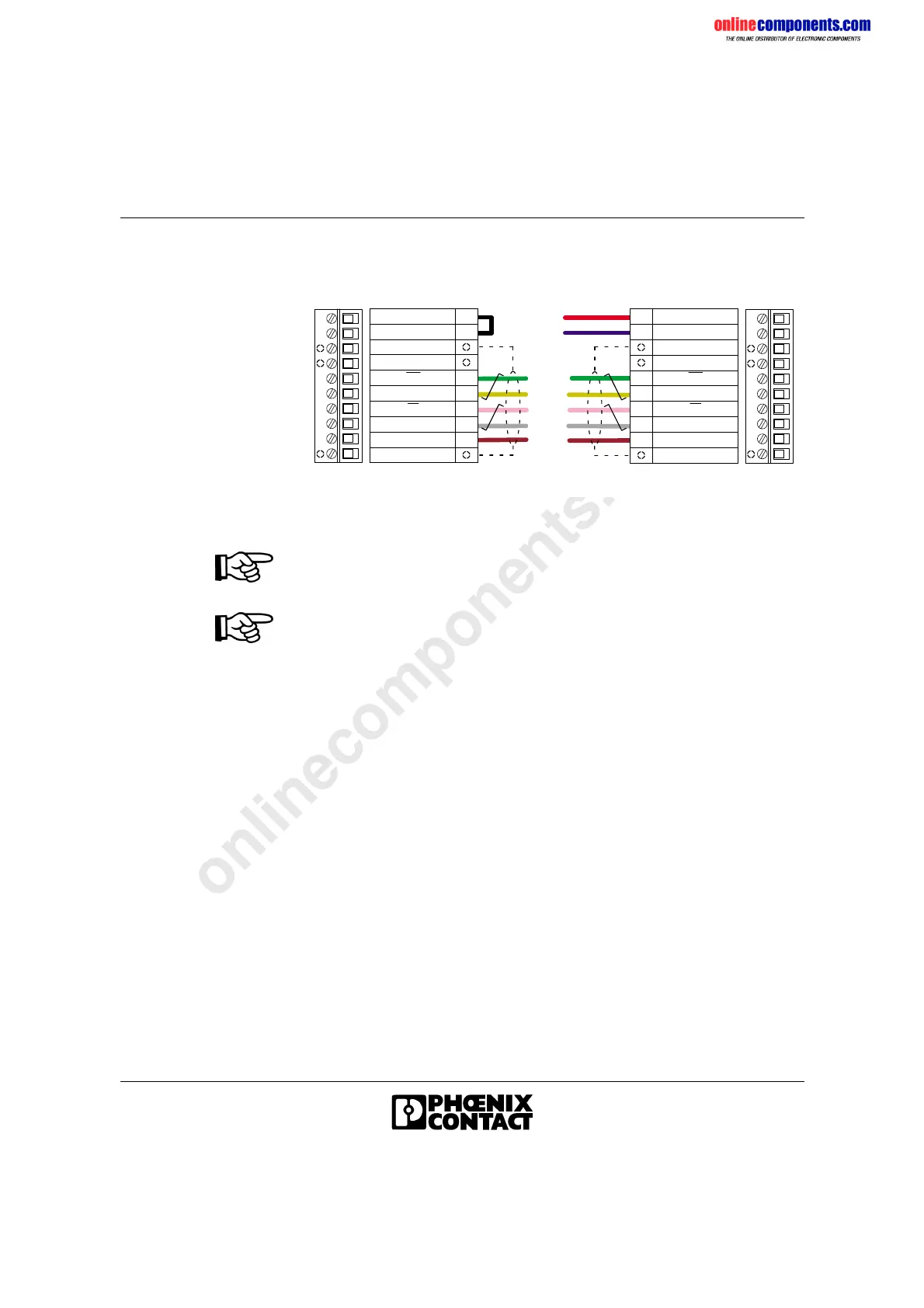
Figure 1-16 Pin assignment of the MINI-COMBICON connectors
A jumper must be installed between the contacts L and M of the outgoing
remote bus connector (Remote OUT). The jumper indicates that another
module follows.
• The supply voltage U
L
for the module electronics must be separately
supplied through the terminals U
L
+ U
L
- of the REMOTE IN connector
as it is not carried in the bus cable.
• Connect the shield clamp to the corresponding contacts of the
connectors. The clamp ensures proper strain relief (Figure 1-15, C or
D).
• Fasten the shield clamp so that as much of the braided shield as
possible is held underneath the clamp.
Plugging the MINI-COMBICON Connectors
• Plug the connectors into the corresponding terminal strips, so that the
keying tabs match.
Remote IN designates the incoming remote bus.
Remote OUT designates the outgoing remote bus.
g r e e n
p i n k
y e l l o w
g r a y
b r o w n
D O
D I
G r o u n d
F
G
H
J
K
D I
D O
L M F G H J K
L
M
S h i e l d
V C C
R B S T
D O
D I
G r o u n d
A
B
C
D
E
D I
D O
A B C D E
U L + U L -
U L +
U L -
S h i e l d
0 V
2 4 V
*
T h i s j u m p e r s h o u l d o n l y b e u s e d i f
a n o t h e r m o d u l e f o l l o w s .
*
O u t g o i n g r e m o t e
b u s ( R E M O T E O U T )
I n c o m i n g r e m o t e
b u s ( R E M O T E I N )
6 0 5 7 A 0 1 6
S h i e l d / S t r a i n r e l i e f
S h i e l d / S t r a i n r e l i e f
S h i e l d / S t r a i n r e l i e f
S h i e l d / S t r a i n r e l i e f
 Loading...