onlinecomponents.com
IBSL SYS PRO UM E
1-22 6057AC01
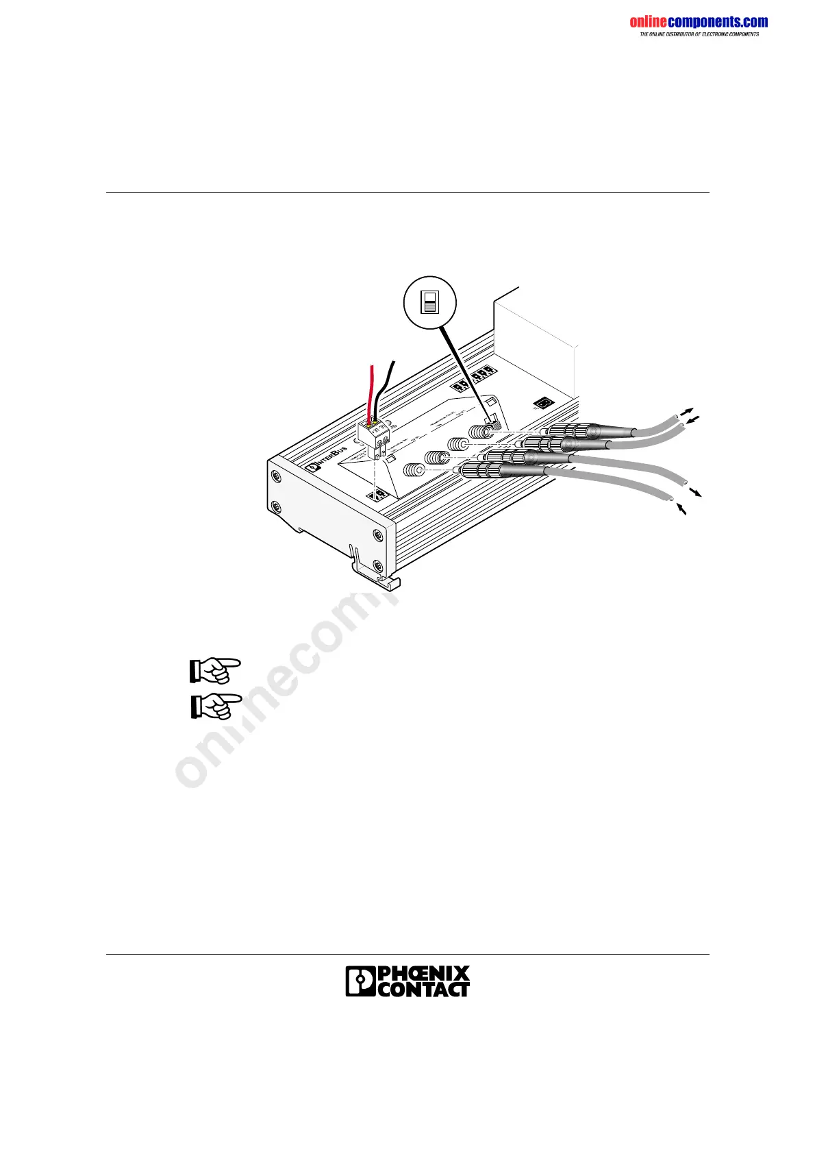
1.8.2 Connecting the Remote Bus With Fiber Optics
(BK Module With IP 20 Protection)
Figure 1-17 Connecting the bus with fiber optics
If modules are followed by another module, the NEXT-END switch must be
set to NEXT. The switch of the last module must be set to END.
Refer to the package slips of the F-SMA connectors and the “Optical Fiber
Installation Guidelines” (DB GB IBS SYS FOC ASSEMBLY, Part No.
94 23 43 9) when assembling fiber optics.
• Fit the corresponding F-SMA connectors to the fiber-optic cables.
• Plug the connectors into the sockets provided.
• Secure the connections with cap nuts.
• Connect the supply voltage U
L
for the module electronics with the
2-pos. MINI-COMBICON connectors.
6 0 5 7 A 0 1 7
+
-
U
L
I n c o m i n g
r e m o t e b u s
O U T
O u t g o i n g
r e m o t e b u s
E N D
N E X T
I N
I N
O U T
 Loading...