onlinecomponents.com
IBSL SYS PRO UM E
1-40 6057AC01
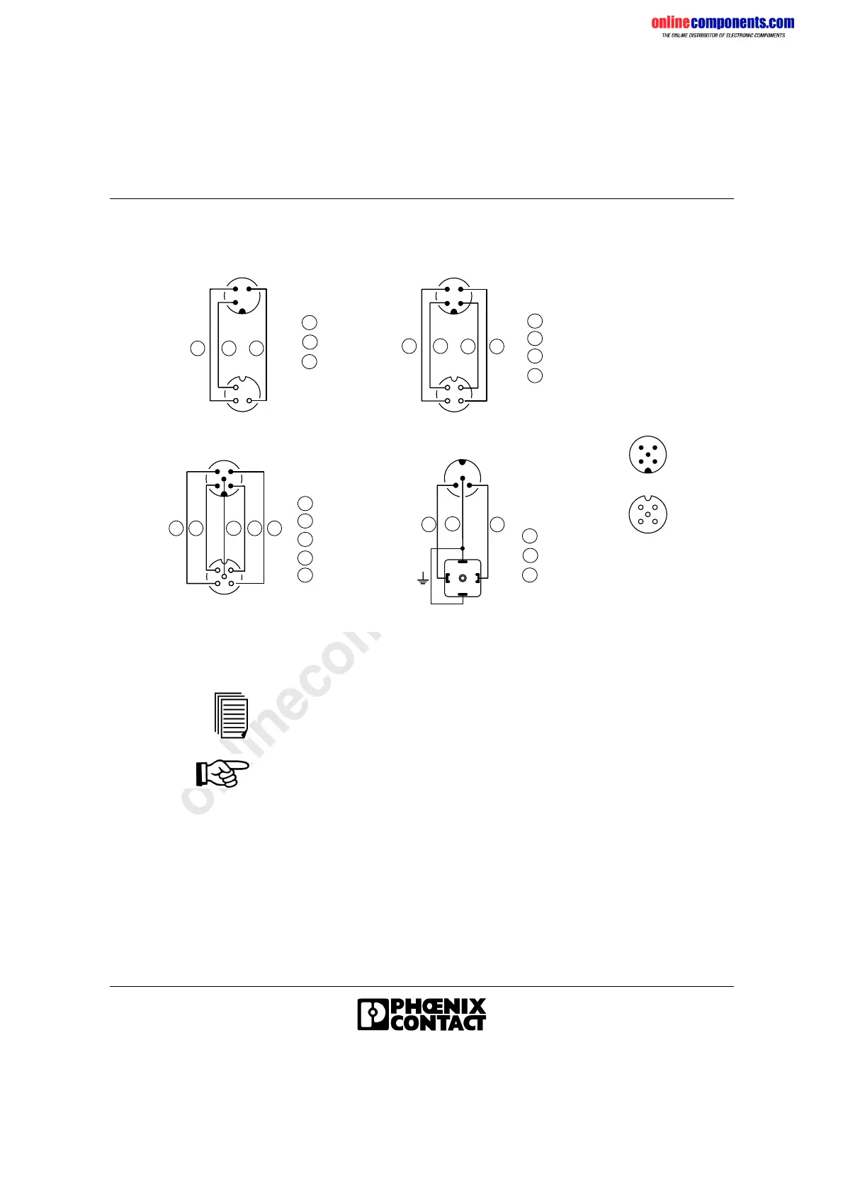
1.9.1 Wiring the Sensor/Actuator Cables
Figure 1-34 Pin assignment of the male and female connectors
For the meaning of the product designations please refer to the ordering
data (see page 1-46).
Note for the IBSL BOX TEMP 2/2 M12 module:
To ensure measuring signal detection at modules only use M12 male
connectors with gold-plated contacts from hardware revision 01 or later!
+ 2 4 V D C
0 V
S i g n a l
M a l e
c o n n e c t o r
F e m a l e
c o n n e c t o r
6 0 5 7 A 0 3 4
1 34
F r o n t v i e w
( n o t s o l d e r s i d e )
3 4
1
3
4
1
4
3
2
+ 2 4 V D C
0 V
S i g n a l
1
4
3
S i g n a l
2
S A C - 3 P - M 1 2 / M S / x x - P U R / M 1 2 F x S A C - 4 P - M 1 2 / M S / x x - P U R / M 1 2 F x
1 34 2
+ 2 4 V D C
0 V
S i g n a l
1
4
3
S i g n a l
2
S A C - 5 P - M 1 2 / M S / x x - P U R / M 1 2 F x
F E
5
S A C - 3 P - M 1 2 / M S / x x - P U R / A - 1 L - S
5
0 V
S i g n a l
F E
3
5
4
5
 Loading...