27
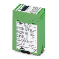
Current/voltage input
Input signal
0…10 V / 0…20 mA
Cut-off frequency 10 Hz
Ascent time (10-90 %)
25 ms
Output
Output signal 0…10 V / 10…0 V, 0…5 V / 5…0 V oder
0(4)…20 mA / 20…0(4) mA
Max. output signal current/voltage
25 mA / 12.5 V
Load current/voltage ≤ 500 Ω / ≥ 500 Ω
Alignment zero point / end value
± 25 % / ± 25 %
Switching output
PNP transistor output, switches the
supply voltage to terminal SW, can carry
a load of 100 mA, not short-circuit proof
General data
Supply voltage 20 ... 30 V DC
Current consumption (without load) < 60 mA (without switching output)
Transmission error
< 0.15 % of end value (typ. 0.1 %)
Temperature coefficient
< 0.015 %/K (typ. 0.01%/K)
Test voltage: input/power supply
input/output
output/power supply
1.5 kV, 50 Hz, 1 min.
1.5 kV, 50 Hz, 1 min.
1.5 kV, 50 Hz, 1 min.
Protection circuit transient protection, polarity protection
Ambient temperature range
-20 °C to +65 °C
Operation indicator
LC display
Control panel
membrane keypad with 3 keys and LCD
Installation position/assembly
any, preferably horizontal
Dimensions (W / H / D) in mm
45 / 75 / 110
Type of connection
pluggable screw connection
Conductor cross section 0.2 – 2.5 mm
2
(AWG 24-14)
Type of housing
ASA-PC (V0)
Conformity / Approvals
c
Conformance with EMC directive
2004/108/EC
Immunity to interference according to EN 61000-6-2
Noise emission according to
EN 61000-6-4
Approval
U
LISTED
PROCESS CONTROL EQUIPMENT
FOR HAZARDOUS LOCATIONS
31ZN
Class I Div 2 Groups A, B, C, D
A) This equipment is suitable for use in Class I, Division 2, Groups A, B, C
and D or non-hazardous locations only.
B) WARNING - explosion hazard - substitution of components may
impair suitability for Class 1, Division 2.
C) WARNING - explosion hazard - do not disconnect equipment unless
power has been switched off or the area is known to be non-hazardous.
8. Technical data
MCR-F-UI-DC 2814605
9000681_05_f_ui.book Seite 27 Freitag, 13. Mai 2011 3:21 15
 Loading...