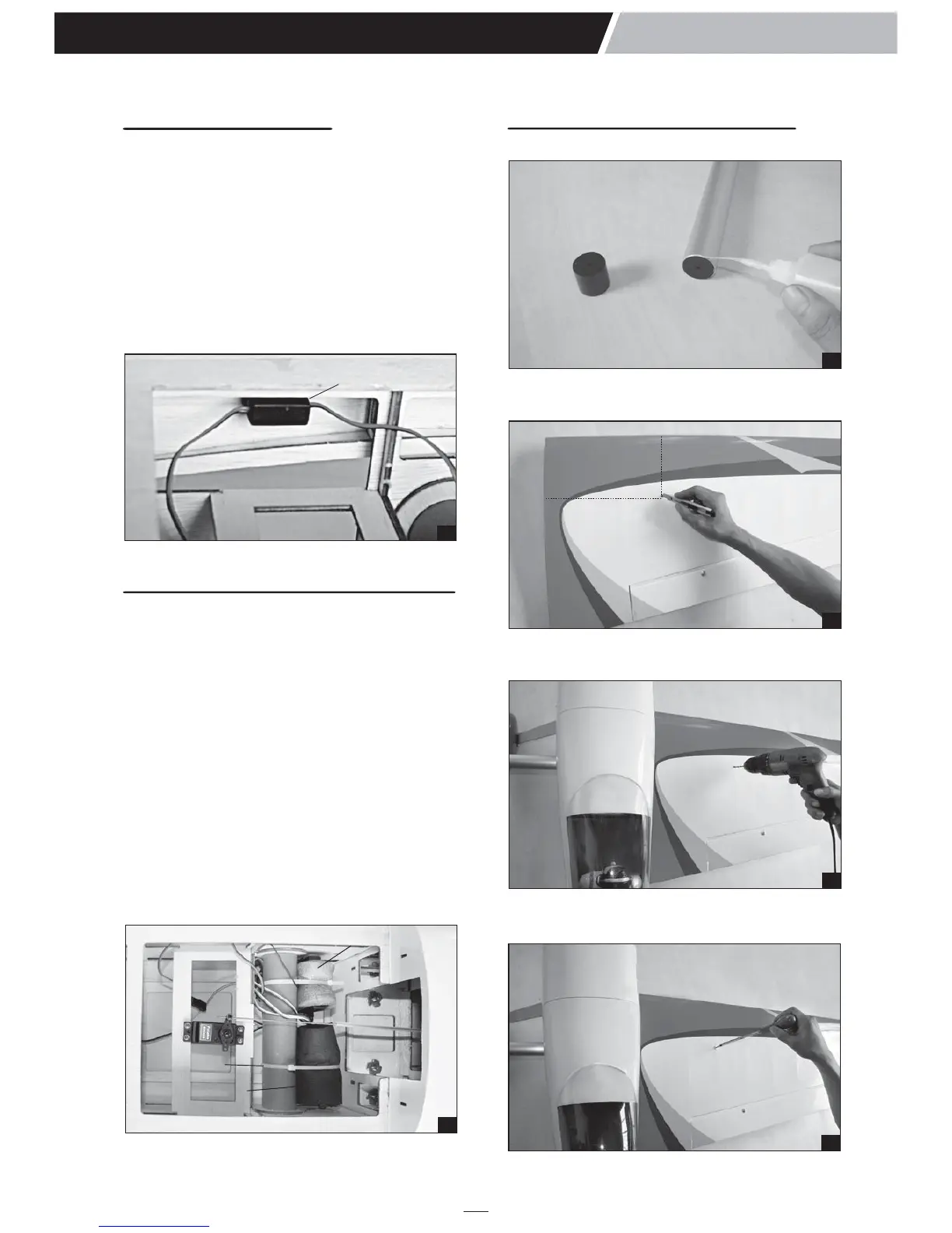
1. Glue the plastic part to the wing joiner.
2. Find the hole on the top of the wing by taking
measurements as picture below.
3. Drill through the mark you make with a 2.5mm
drill bit (Note: just through the wing joiner).
4. Secure the wing joiner using a 3mm x 25mm
wood screw.
48
Switch
INSTALLING THE SWITCH
1. The switch should be mounted on the fuselage
side, opposite the muffler, close enough to the
receiver so the lead will reach. Use the face
plate of the switch cut out and locate the
mounting holes.
2. Cut out the switch hole using a modeling knife.
Use a 2mm drill bit and drill out the two
mounting holes through the fuselage side.
3. Secure the switch in place using the two
machine screws provided with the radio
system.
t
INSTALLING THE RECEIVER AND BATTERY
1. Plug the servo leads and the switch lead into
the receiver. You may want to plug an aileron
extension into the receiver to make plugging in
the aileron servo lead easier when you are
installing the wing. Plug the battery pack lead
into the switch.
2. Wrap the receiver and battery pack in the
protective foam to protect them from vibration.
Use a rubber band or masking tape to hold the
foam in place.
3. Position the battery pack and receiver in place
and using the two zip ties for mounting them as
the picture below.
4. Using a 2mm drill bit, drill a hole through the
side of the fuselage, near the receiver, for the
antenna to exit.
13
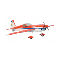
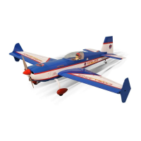
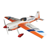
EXTRA 300S
Instruction Manual
49
Battery
Zip tie
Receiver
INSTALLING and secure the wing
50
52
53
51
250mm
145mm