7
9
↑
WING TIP
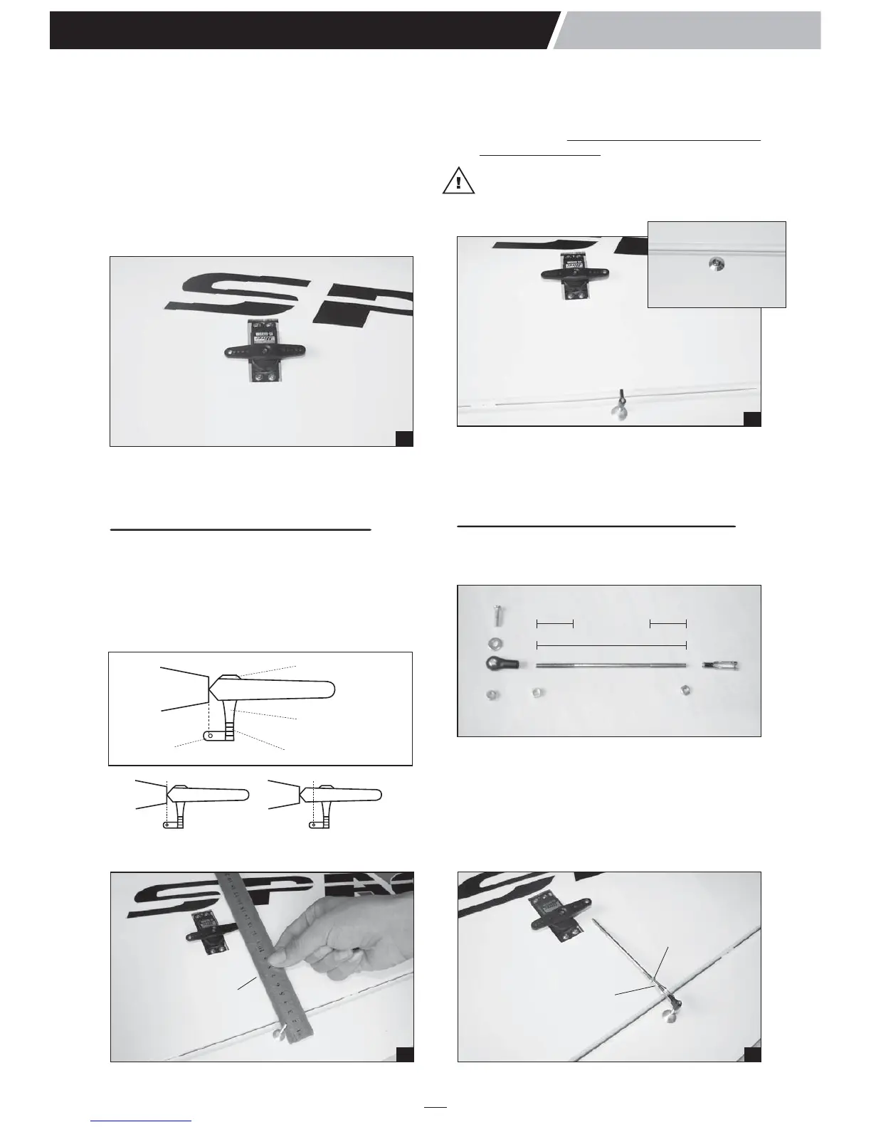
6. Temporarily position the aileron servo into the
servo bay. Drill a 1.6mm hole through the four
mounting holes of the servo, drilling through the
plywood mounting plate in the wing. Install and
remove a servo mounting screw into each of the
four holes. Insert a drop of thin CA into the
holes to harden the wood. After the glue has
cured, install the servo into the servo bay using
the hardware that came with your servo. Center
the servo and install a servo arm as shown.
7. Repeat step # 1 - # 6 to install the second
aileron servo in the opposite wing half.
3. Repeat step # 1 - # 2 to install the control horn
on the second aileron.
INSTALLING THE AILERON LINKAGES
The aileron linkages are assembled as shown
below.
1. Locate the pushrod wire. Slide a silicon clevis
retainer onto a clevis. Screw a M3 nut and a
threaded metal clevis onto the threaded end of
the wire. Tighten the nut against the clevis and
then install the clevis on the aileron control
horn.
INSTALLING THE CONTROL HORNS
1. The aileron has a block wood plate for mounting
the control horn. One aileron control horn in
positioned on each aileron. Using a ruler and a
pen, locate and mark the location of the control
horn. It should be mounted on the bottom side
of the aileron at the leading edge, in line with
the aileron pushrod.
7
4
EXTRA 300S
Instruction Manual
2. Drill through the mark you made with a (3mm)
drill bit. Hard the hole with thin CA. Install the
control horn. Remember use thread locking
compound to secure.
Note: The hole on the nylon horn is aligned
with the hinge line and pushrod is aligned with
the servo arm.
10
M3 nut
M3 clevis
95mm
22mm
22mm
Aluminum washer
Aluminum control
Plastic horn
3mm Screw
RIGHT WRONG
8
IN LINE
↑
WING TIP
↑
WING TIP