7
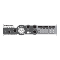
FireFly 302
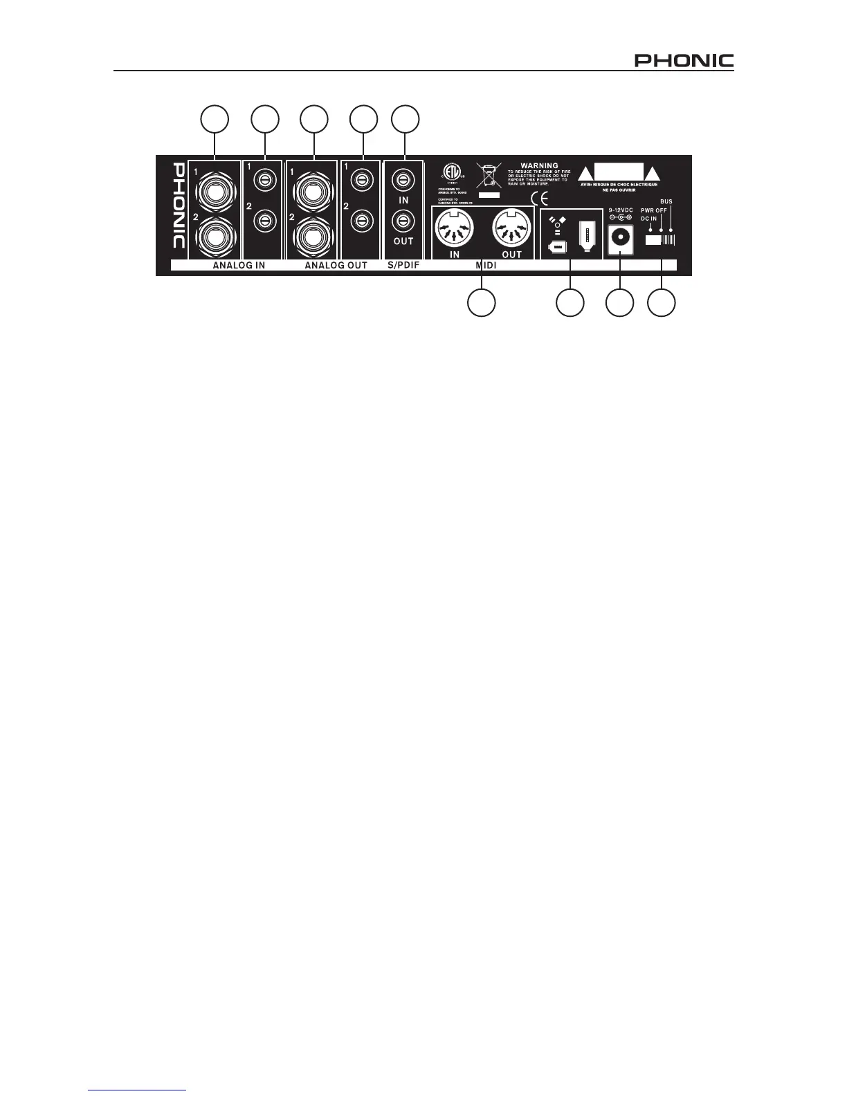
Rear Panel Description
8. Analog 1/4” TRS Inputs 1 and 2
These are balanced 1/4” TRS Line Inputs
and can be used to connect any line level
devices, such as CD players or DAT re-
corders.
9. Analog RCA Inputs 1 and 2
These are RCA inputs and can be used to
connect any device like CD players, DAT
recorders, turntables, and even analog
mixers (taking the signal from a mixer’s
Record or 2-Track outputs).
Important Note: Keep in mind that the two
RCA inputs are completely independent
of one another; however these inputs
should not be used if the 1/4” analog 1
and 2 inputs are used, as doing so may
cause irreversible damage to the FireFly.
You can, however, mix and match these
inputs. If, for example, you wanted to use
RCA input 1 and 1/4” input 2 that would not
cause any problems.
10. Analog 1/4” TRS Outputs 1 and 2
This are balanced 1/4” TRS Line Outputs
with line level signal (+4dBu). Use them to
get a stereo output channel and connect
them to active monitors (such as the Pho-
nic P8A), or perhaps to an amplier and a
passive pair of speakers. You could also
use them with several signal processor or
any external devices.
11. Analog RCA Outputs 1 and 2
These are RCA line outputs. They accept
RCA cables and can be connected to any
external device that uses this connector
type (tape recorders, MP3 recorders,
etc.).
12. S/PDIF In/Out
These are a standard S/PDIF Digital Audio
Input/Outputs that can be use with digital
mixers, DAT recorders, or any external
device that uses RCA Digital interface
format. The S/PDIF’s output sampling rate
is determined by the sampling rate set by
the FireFly control software. Please use a
75 ohms coaxial cable with RCA plug if you
are using the S/PDIF connection, as the
most common problems associated with
glitches in digital interfaces are the result
of use of using poor quality cable.
8
9
10 11
12
13 14 15 16