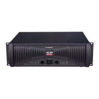
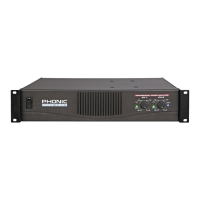
INSTALLATION
MOUNTING
The
power amplifier can be installed in a standard 19-
inch
equipment rack. It requires 3 units (5.25 inches)
for
the XP 2000/2100, XP 3000/3100, and 2 units (3.5
inches)
for the XP600/1000 of vertical rack space and
secures
to the rack cabinet with four rack mount
screws
and cup washers. In a rack, it is best to mount
units
one above the other, with at least a unit of space
at
least between two amplifiers. This provides efficient
airflow
and support.
COOLIN
G
Two variable-speed fans would start running as soon
as
the power is being turned on. Before mounting your
amplifier, you should familiarize yourself with its cool-
ing
requirements.
The
air flows from the front to the back, so it is impor-
tant not to block the amplifier front air vents. If the
amplifier
is rack-mounted, leave some space in front
of
the rack to prevent heated air being drawn back
into
the front-to-back airflow.
Airflow
restrictions are the most common cause of
inadequate
cooling. They may result from improper
mounting,
bundles of power cords, clogged dust fil-
ters
and closed rack doors. Mount the amplifier to
allow
sufficient airflow out the front outlets to ensure
your
amplifier work properly.
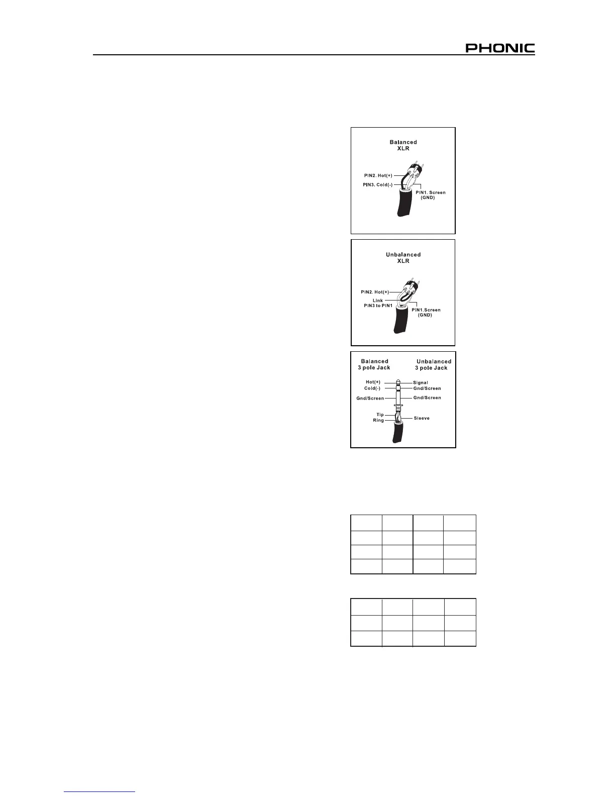
WIRIN
G
The
balanced XLR and TRS input connectors will ac-
cept
the line-level output of most devices for ultimate
input
convenience. The amplifier built-in XLR and TRS
connectors
can be wired similarly for balanced or un-
balanced,
floating or ground-referenced sources. The
output
connector is a binding post with Speakon which
provides
an easy connection when using
banana
plugs, spade lugs or bare wires.
SPEAKON PIN OUT
PI
N PIN
PI
N PIN
1+ 1
1
1+
1+
1-
1-
BRG
+ BRG-
2
2
2
2
2-
2-
2+
2+
2+
NA
NA
CH
2
CH
CH
CH
CH
CH
1
INPUT WIRING
OUTPUT WIRIN
G
5
XP 600/1000/2000/2100/3000/3100