13
3.8 Setting Motor Limits
The motor limits are set manually with the hex screw driver provided or with a tool that the installer uses to set switch
motors with.
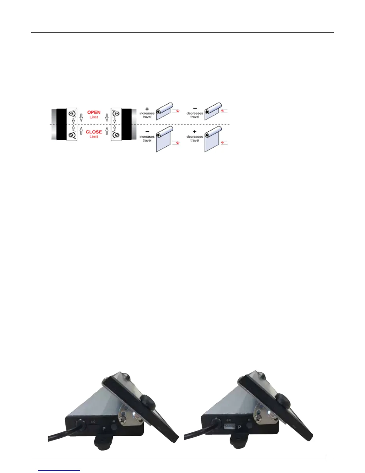
Below is a table that shows a motor positioned on the left or right side of the tube and the direction to turn the hex
screw to adjust the top and bottom limits.
The Solar receiver unit is supplied with enough charge from the factory to enable limit settings and several days of
operation before Sunlight is required to re-charge the battery.
To set the Top limit, press the UP button on the remote control, as the blind starts to move, turn the OPEN limit on the
motor head using the Hex driver tool to increase or decrease the limit. If you continually turn the limit fast enough (by
hand using the tool) the awning upper limit will creep up in small increments. If the power times out, select the channel
button on the remote control and press the UP button again.
Remember the green LED light must be illuminated on the remote control after selecting the correct channel for the
motor to respond.
Complete the same process above, but in the down position on the remote and using the Close limit Hex screw on the
motor head to set the bottom limit.
3.9 Dry contact/ Automation
Home automation is supported via the use of dry contact (Open, Common, Close); the port for dry contact is located on
the side of the battery pack / receiver.
Each unit will be supplied with a dry contact cable that plugs into the battery pack / receiver for home automation
control.
There is a rubber cap that sits over the dry contact port to protect it from water and debris; this will need to be removed
before the dry contact cable can be plugged in.
Limit settings can be adjusted using a limit setting tool,
hex key or flat head screwdriver. Power must be supplied
to the motor in the direction required in order to set the
limits. Turn the limit screws in the direction indicated
above to increase or decrease blind travel.
Installation / Setup