Do you have a question about the Pike Evolution Series and is the answer not in the manual?
Introduces the Evo series, its history, flexibility, and applications in portable traffic control systems.
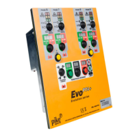
Details the controls and indicators of the Evo PT5 controller panel, explaining its functions.
Describes complementary panels like Evo PT4+, T5, and T2 controllers and their capabilities.
Guidance on positioning signal heads according to traffic management schemes and relevant references.
Step-by-step guide for configuring slave controllers for vehicle and pedestrian phases.
Explains vehicle and pedestrian head designations and abbreviations used on the text display.
Using the SCAN option to find the first available clear radio channel.
Steps for powering on the master controller and selecting radio channel/power.
Configuring timings and modes for vehicle phases on the master controller.
Configuring timings and modes for pedestrian crossings on the master controller.
Procedures for initiating system operation and performing a test start.
Guide to using the PEDESTRIAN ONLY feature for maximum traffic efficiency.
Instructions for optionally joining vehicle phases 1&2 or 3&4 for coordinated operation.
Guidelines for using channels when mixing MULTI and standard Evo controllers.
Procedure to scan for and select a clear radio channel for reliable communication.
How to check the current radio channel while the system is running.
Steps to reduce transmitter power to resolve communication issues between nearby installations.
Guidance on adjusting phase timings to optimize traffic flow and clear queues.
Adjusting ALL RED settings for slow vehicles not clearing works effectively.
Adjusting MAX GREEN settings for vehicles taking multiple green periods.
Explains different operation modes: MANUAL, VEHICLE, FIXED TIME, and CUSTOM.
System response and recovery process for temporary communication loss.
Actions and system behavior following a sustained loss of communication.
How to invoke 'hold all red' mode from a remote slave controller.
How to invoke 'hold all red' mode directly from the master controller.
Steps to exit the 'hold all red' state and resume normal operation.
Procedure to check battery charge levels for master and all slave controllers.
Steps for curing, acknowledging, and resetting the system after an error.
Procedure for safely powering down and removing the signal system.
Responses to red signal failures in vehicle and pedestrian setups.
System reaction to simultaneous green signals on opposing phases.
Interpretation of indicators for fault tracing and communication status.
Reference for alphanumeric status codes and error messages displayed by the controller.
Guidance on troubleshooting based on flashing indicators and text display codes.
Information on materials and actions for end-of-life disposal of the Evo controller.
Explains conventions and shows basic setup examples for phases and modes.
Shows a carriageway controlled by two single-approach phases.
Demonstrates a basic pedestrian crossing using PEDESTRIAN ONLY mode.
Shows a pedestrian crossing with two vehicle heads per approach for visibility.
Illustrates a pedestrian crossing combined with shuttle working scenarios.
Shows staggered pedestrian crossings across two carriageways using PEDESTRIAN ONLY.
Depicts a crossroad with linked vehicle phases and four pedestrian crossings.
Illustrates a crossroad controlled by four vehicle phases and four pedestrian crossings.
Shows a major junction controlled by five vehicle phases and four pedestrian crossings.
Demonstrates shuttle working control on a fast carriageway with a side road.
| Connectivity | Wired |
|---|---|
| Output Current | 500mA |
| Communication Interface | USB 2.0 |
| Platform | PC |
| Buttons | 12 |
| D-pad | 8-way |
| Vibration | Dual vibration motors |
| Input Voltage | 5V |
| Operating Temperature | 0°C to 40°C |