Do you have a question about the Pilz PNOZ X4 and is the answer not in the manual?
Information on the validity period of the product documentation.
Guidance on how to effectively use the product manual.
Explanation of warning symbols and their meanings.
Specifies the approved applications and purpose of the safety relay.
Outlines relevant safety standards and compliance requirements.
Guidance on performing safety assessments for the product in its application.
Requirements for personnel involved in assembly, installation, and operation.
Conditions that invalidate warranty claims and limit liability.
Guidelines for the proper disposal of the product.
Important notes and precautions for safe operation.
Describes the built-in safety mechanisms and redundancy.
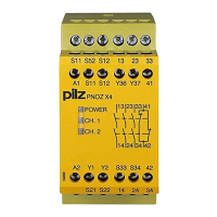
Visual representation of the unit's internal connections and terminals.
Explains different operating modes like single-channel and dual-channel.
Specifies conditions for installing the unit in control cabinets and on DIN rails.
Important considerations for connecting the unit's terminals and cables.
Procedure for testing the shorts across contacts detection function.
Shows wiring diagrams for different input circuit configurations.
Procedures and frequency for checking the safety function.
Explanation of the LEDs indicating operating status and errors.
Describes common faults like earth faults and contact malfunctions.
Overview of product approvals and general specifications.
Detailed electrical characteristics including voltage, current, and power.
Specifications related to the unit's input circuits and parameters.
Specifies characteristics and utilization categories for the output contacts.
Lists various timing parameters like switch-on delay and recovery time.
Covers operating conditions, EMC, vibration, and protection types.
Provides physical dimensions, materials, and mounting details.
| Supply Voltage | 24 V DC |
|---|---|
| Contacts | 3 N/O, 1 N/C |
| Width | 45 mm |
| Depth | 121 mm |
| Mounting | DIN rail |
| PL according to EN ISO 13849-1 | PL e |
| Category according to EN 954-1 | 4 |
| SIL according to IEC 61508 | SIL 3 |
| Max. switching current | 6 A |
| Protection class | IP20 |
| Operating Temperature | -10 °C to +55 °C |
| Stop Category | 0 |
| SIL CL according to EN IEC 62061 | SIL CL 3 |
| Number of safe inputs | 2 |
| Number of safe outputs | 3 |
| Operating temperature range | -10 °C to +55 °C |