- 4 -
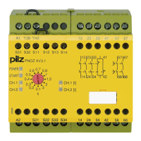
To operate:
• 24 V DC:
Connect the operating voltage to terminals
A1 and A2.
24 ... 240 V AC/DC:
Connect the operating voltage to terminals
A1 and A2.
Connect the operating earth terminal
with the ground earth (Earth fault
monitoring).
• Reset circuit:
- Automatic reset: Bridge S13-S14
- Manual reset with monitoring: Connect
button to S33-S34 (S13-S14 open).
• Input circuit:
- Single-channel: Bridge S21-S22 and
S31-S32. Connect N/C contact from
safety switch (e.g. Emergency-Stop) to
S12 and S11.
- Dual-channel, without short circuit
detection: Link S21-S22. Connect N/C
contact from safety switch
(e.g. emergency stop) to S11-S12 and
S11-S32
- Dual-channel, with short circuit
detection: Bridge S11-S12. Connect N/C
contact from safety switch
(e.g. emergency-stop) to S21-S22 and
S31-S32.
• Reset delay-on-de-energisation
Connect a button to Y39-Y40 or link Y39-
Y40
• Feedback control loop:
Connect external relays/contactors in
series to reset circuit S13-S14 or S33-S34
The safety contacts are activated (closed)
and the auxiliary contact (41-42) is open. The
status indicators "CH.1","CH.2", "CH.1(t) and
"CH.2(t)" are illuminated. The unit is ready for
operation. If the input circuit is opened, the
safety contacts 13-14/23-24/33-34 open and
the auxiliary contact 41-42 closes. The status
indicators "CH.1" and "CH.2" extinguish.
After the delay-on-de-energisation period the
saftey contacts 57-58/67-68 open and the
status indicators "CH.1(t)2 and "CH.2(t)"
extinguish.
Reactivation
• Close the input circuit.
• For manual reset with monitoring, press
the button and release between S33-S34.
The status indicators light up again, the
safety contacts are closed.
Application
In Fig. 2 ...Fig. 11 are connection examples
for Emergency Stop wiring with automatic
and monitored reset. Safety gate controls as
well as contact expansion via external
contactors.
• Fig. 2 and 7: S33-S34 not connected
Please note: The device starts
automatically after loss of power. You
should prevent an unintended start-up by
using external circuitry measures.
• Fig 3, 4, 5, 6, 9: S13-S14 not connected
• Fig. 7: Automatic reset with safety gate
control: with the safety gate open the unit
is ready for operation via reset circuit S13-
S14. After closing the safety input circuit
S21-S22 and S31-S32 the safety contacts
will close.
Mise en oeuvre :
• 24 V DC:
amener la tension d’alimentation sur A1 et
A2
24 ... 240 V AC/DC:
amener la tension d’alimentation sur A1 et
A2
Relier la borne terre (Contrôleur
d’isolement).
• Circuit de réarmement:
- réarmement automatique: pontage des
bornes S13-S14
- réarmement manuel auto-côntrolé:
câblage d'un poussoir sur S33-S34
(S13-S14 ouvert).
• Circuits d’entrée:
- Commande par 1 canal : câblage du
contact à ouverture entre S11-S12,
pontage entre S21-S22 et S31-S32
- Commande par 2 canaux sans détection
des courts-circuits: câblage des contacts
à ouverture entre S11-S12, S11-S32,
pontage entre S21-S22
- Commande par 2 canaux
avec détection
des courts-circuits: câblage des contacts
à ouverture entre S21-S22 et S31-S32,
pontage entre S11-S12
• Reset de la temporisation
Poussoir ou pont sur les bornes Y39-Y40
• Boucle de retour:
câbler les contacts des contacteurs
externes en série dans le circuit de
réarmement S13-S14 ou S33-S34
Les contacts de sécurité se ferment et le
contact d'information 41-42 s'ouvre. Les
LEDs "CH.1", "CH.2", "CH.1(t)" et "CH.2(t)"
sont allumées. L’appareil est prêt à
fonctionner.
Si le circuit d’entrée est ouvert, les contacts
de sécurité 13-14/23-24/33-34 retombent et
le contacts d'information se ferme. Les LEDs
"CH.1" et "CH.2" s'éteignent. À la fin de la
temporisation, les contacts de sécurité 57-58/
67-68 retombent et les LEDs "CH.1(t)" et
"CH.2(t)" s’éteignent.
Remise en route :
• fermer le circuit d’entrée
• en cas de surveillance du circuit de
réarmement, appuyer le poussoir de
validation S33-S34.
Les affichages d'état s'allument à nouveau.
Les contacts de sécurité sont fermées.
Utilisation
Les figures 2 à 11 représentent les différents
câblages possibles du PNOZ XV3.1P à savoir:
poussoir AU avec réarmement automatique ou
auto-côntrolé, interrupteurs de position et
augmentation du nombre des contacts de
sécurité par contacteurs externes.
• Fig. 2 et 7: pas de câblage sur S33-S34
Dans le cas, l’appareil se réarme
automatiquement après une coupure et
une remise sous tension. Evitez tout risque
de redémarrage par un câblage externe
approprié.
• Fig. 3, 4, 5, 6, 9:
pas de câblage sur S13-S14
• Fig. 7: Réarmement automatique en cas
de surveillance protecteur: lorsque le
protecteur est ouvert, le circuit S13-S14 se
ferme et le relais est prêt à fonctionner.
Dès la fermeture des canaux d'entrée S21-
S22 et S31-S32, les contacts de sortie du
relais se ferment.
Ablauf:
• 24 V DC:
Versorgungsspannung an Klemmen A1
und A2 anlegen.
• 24 ... 240 V AC/DC: Versorgungsspannung
an Klemmen A1 und A2 anlegen.
Betriebserdungsklemme mit Schutz-
leitersystem verbinden (Erdschluss-
erkennung).
• Startkreis:
- Automatischer Start: S13-S14 brücken.
- Manueller Start mit Überwachung: Taster
an S33-S34 anschließen (S13-S14 offen)
• Eingangskreis:
- Einkanalig: S21-S22 und S31-S32
brücken. Öffnerkontakt von Auslöse-
element an S11 und S12 anschließen.
- Zweikanalig ohne Querschluss-
erkennung: S21-S22 brücken. Öffner-
kontakt von Auslöseelement an S11-
S12 und S11-S32 anschließen.
- Zweikanalig mit Querschlusserkennung:
S11-S12 brücken. Öffnerkontakt von
Auslöseelement an S21-S22 und S31-
S32 anschließen.
• Reset Verzögerungszeit
Taster oder Brücke an Y39-Y40 anschließen
•
Rückführkreis:
Externe Schütze in Reihe zu Startkreis
S13-S14 bzw. S33-S34 anschließen.
Die Sicherheitskontakte sind aktiviert (ge-
schlossen) und der Hilfskontakt 41-42 ist
geöffnet. Die Statusanzeigen für "CH.1", "CH.
2", "CH.1(t)" und "CH.2(t)" leuchten. Das
Gerät ist betriebsbereit.
Wird der Eingangskreis geöffnet, öffnen die
Sicherheitskontakte 13-14/23-24/33-34 und
der Hilfskontakt schließt. Die Statusanzeigen
"CH.1" und "CH.2" erlöschen. Nach Ablauf
der Verzögerungszeit öffnen die Sicherheits-
kontakte 57-58/67-68 und die Statusan-
zeigen "CH.1(t)" und "CH.2(t)" erlöschen.
Wieder aktivieren
• Eingangskreis schließen.
• Bei manuellem Start mit Überwachung
Taster zwischen S33 und S34 betätigen.
Die Statusanzeigen leuchten wieder, die
Sicherheitskontakte sind geschlossen.
Anwendung
In Fig. 2 ... Fig. 11 sind Anschlussbeispiele
für Not-Halt-Beschaltung mit automatischem
und überwachtem Start, Schutztüran-
steuerungen sowie Kontaktvervielfachung
durch externe Schütze dargestellt.
Bitte beachten Sie:
• Fig. 2 und 7: keine Verbindung S33-S34
Beachten Sie: Das Gerät startet bei
Spannungsausfall und -wiederkehr
automatisch. Verhindern Sie einen
unerwarteten Wiederanlauf durch externe
Schaltungsmaßnahmen.
• Fig. 3, 4, 5, 6, 9:
keine Verbindung S13-S14
•
Fig. 7: Automatischer Start bei Schutztür-
steuerung: Das Gerät ist bei geöffneter
Schutztür über den Startkreis S13-S14
startbereit. Nach Schließen der Eingangs-
kreise S21-S22 und S31-S32 werden die
Sicherheitskontakte geschlossen.

 Loading...