Do you have a question about the Pilz PNOZ XV3.1 and is the answer not in the manual?
This documentation is valid for the product PNOZ XV3.1 until new documentation is published.
This document is intended for instruction. Only install and commission the product if you have read and understood this document.
Identifies important information, including DANGER, WARNING, CAUTION, and NOTICE warnings.
The safety relay PNOZ XV3.1 provides a safety-related interruption of a safety circuit, used in applications with E-STOP and safety gates.
Covers safety assessment requirements, including Machinery Directive and EN ISO 13849 standards.
A safety assessment in accordance with the Machinery Directive is required before device installation and use.
Products must be handled only by competent persons with specialist knowledge and training.
Claims invalid if product misused, damaged, or modified. Personnel must be qualified.
Comply with local regulations for electronic device disposal, especially in safety-related applications.
Unit meets safe operation conditions; note overvoltage category III and insulation voltage requirements.
Redundant circuit, self-monitoring, and automatic testing of safety function relays ensure safety.
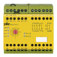
Describes relay outputs, connection options for E-STOP, safety gates, start buttons, and LED indicators.
Terminal configuration diagrams for AC/DC types, showing power and input connections.
Terminal configuration diagrams for DC types, showing power and input connections.
Describes LED status and safety contact states for closed/opened input circuits.
Details single-channel/dual-channel operation, automatic/monitored start, and contact expansion.
Explains reset function and delay time setting for safety contacts.
Explains symbols and abbreviations for timing diagrams of POWER, Start, Reset, Input, and Output signals.
Details unit installation in control cabinets and securing to DIN rails.
Notes on wiring, terminal status, output types, fuse protection, and EMC measures.
Test procedure for detecting shorts across contacts, including fuse triggering and reset.
Illustrates connection diagrams for supply voltages (UB 24-240 VAC/DC and UB 24 VDC).
Shows wiring for E-STOP and safety gate inputs in single-channel and dual-channel configurations.
Diagrams for E-STOP and safety gate start circuits, including automatic and monitored start options.
Explains reset delay options (link/N/C) and feedback loop configurations with external contactors.
Details required checks for safety contacts on relay outputs to ensure correct opening/closing.
Explains the meaning of POWER, START, CH.1, CH.2, CH.1 [t], and CH.2 [t] LEDs.
Covers earth faults, contact malfunctions, LED errors, and delay-on de-energisation contact behavior.
Diagram showing the external dimensions of the unit in millimeters.
Details certifications, voltage, tolerance, output power, and input/output current specifications.
Lists contact types, number of contacts, and max. short circuit current for order numbers.
Specifies utilization categories (AC1, DC1) for instantaneous and delayed safety contacts.
Specifies utilization categories (AC1, DC1) for auxiliary contacts.
Details utilization categories (AC15, DC13) for safety contacts per EN 60947-5-1.
Details utilization categories (AC15, DC13) for auxiliary contacts.
Covers UL utilization, fuse protection for safety/delayed contacts, and circuit breaker specs.
Specifies fuse protection requirements for auxiliary contacts.
Details contact material and conventional thermal current ratings for various load conditions.
Lists typical/maximum switch-on delays and delay-on de-energisation times.
Specifies delay time options, time accuracy, repetition accuracy, and waiting periods.
Details climatic suitability, temperature ranges, humidity, and EMC compliance standards.
Covers vibration, airgap creepage, overvoltage category, pollution degree, and protection types.
Describes material, connection types, mounting, and conductor cross-section specifications.
Provides detailed dimensions (height, width, depth) and weight for the unit.
Details electrical specs: duty cycle, voltage, current, cable resistance for specific models.
Specifies utilization categories (AC1, DC1) for safety and auxiliary contacts for specific order numbers.
Details utilization categories (AC15, DC13) for delayed safety and auxiliary contacts.
Covers UL utilization, fuse protection for contacts, and contact material specifications.
Lists thermal current ratings per contact and switch-on delay times for different operating modes.
Details delay-on de-energisation times, power failure times, and recovery times.
Covers climatic suitability, temperature ranges, EMC, vibration, protection types, mounting, and mechanical life.
Provides detailed dimensions (height, width, depth) and weight for the unit.
Presents safety characteristic data (PL, SIL CL) and notes on achieving required safety levels for plants/machines.
Illustrates service life graphs indicating expected failure cycles due to wear based on switching current and utilization category.
Lists product types, features, connection types, and corresponding order numbers for PNOZ XV3.1 variants.
Confirms compliance with EU Machinery Directive 2006/42/EC, with link to complete declaration.