• AC-Schaltgeräte haben einen kurzschluß-
festen Netztransformator. DC-Schalt-
geräte besitzen eine elektronische
Sicherung.
Funktionsbeschreibung
Das Schaltgerät PNOZ dient dem sicher-
heitsgerichteten Unterbrechen eines Sicher-
heitsstromkreises. Nach Anlegen der Be-
triebsspannung, Brücke zwischen X1-X2 und
T33-T34 sowie geöffnetem Eingangskreis
geht Relais K3 in Wirkstellung.
• Eingangskreis geschlossen (z. B. NOT-
AUS-Taster nicht betätigt)
Relais K1 und K2 gehen über die Schlie-
ßer K3.1 und K3.2 in Wirkstellung und
halten sich selbst über K1.1 bzw. K2.1.
Die Statusanzeigen leuchten. Durch Öff-
nen der Kontakte K1.2 und K2.2 geht K3
nach Ablauf der Rückfallverzögerung von
90 ms in Ruhestellung. Die Sicherheits-
kontakte (13-14/23-24/33-34) sind
geschlossen, der Hilfskontakt (41-42) ist
geöffnet.
• Eingangskreis wird geöffnet (z. B. NOT-
AUS-Taster betätigt)
K1 und K2 fallen in die Ruhestellung
zurück. Die Sicherheitskontakte (13-14/23-
24/33-34) werden redundant geöffnet, der
Hilfskontakt (41-42) geschlossen.
Function Description
The relay PNOZ provides a safety-oriented
interruption of a safety circuit. When the
operating voltage is supplied, X1 - X2 and
T33 - T34 are bridged and the input circuit
is closed, relay K3 energises.
• Input circuit closed (e.g. Emergency Stop
Button not activated):
Relays K1 and K2 energise via the N/O
K3.1 and K3.2 and latch via K1.1/K2.1.
The status indicators illuminate. By
opening the contacts K1.1 and K2.2, K3
de-energises following the delay-on de-
energisation of 90 ms. The safety contacts
(13-14/23-24/33-34) are closed, the signal
contact (41-42) is opened.
• Input circuit opened (e.g. Emergency Stop
Button activated):
K1 and K2 de-energise. The safety
contacts (13-14/23-24/33-34) are opened
redundantly, the signal contact (41-42) is
closed.
• fusible électronique (relais en DC)
Description du fonctionnement
Le relais PNOZ assure de façon sure,
l’ouverture d’un circuit de sécurité. A la mise
sous tension du relais (A1-A2), si X1-X2 et
T33-T34 sont pontés et les canaux d’entrée
ouverts, le relais K3 colle.
• Fermeture des canaux d’entrée T11, T12
& T22 (par ex. AU non actionné) :
les relais K1 et K2 collent par l’inter-
médiaire des contacts K3.1 et K3.2 et
s’auto-maintiennent par K1.1 et K2.1. Les
LEDs de visualisation sont allumées.
L’ouverture des contacts K1.2 et K2.2 fait
retomber le relais K3 qui se maintient
environ 90 ms. Les contacts de sortie de
sécurité (13-14/23-24 et 33/34) se
ferment, le contact d’information 41-42
s’ouvre.
• Ouverture des canaux d’entrée (par ex.
action sur AU)
K1 et K2 retombent. Les contacts de sortie
s’ouvrent de façon redondante, le contact
d’information 41-42 se ferme.
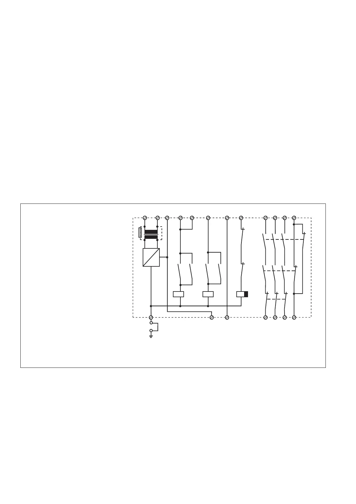
Innenschaltbild
Internal Wiring Diagram
Schéma de principe
~
=
K1.1 K3.1 K2.1 K3.2
K1.2
K2.2
G1
+
F1
K1 K2 K3
A1 (L+)
A2 (L-)
T11
T12
T12
T22
X1
X2
T33
T34
13 23 33 41
14 24 34 42
K1
K3
K2
* Bei Betriebspannung UB~ ist eine lösbare
Verbindung zwischen Gerät und Betriebserde
erforderlich. Der Anschluß entfällt bei UB=.
* Pour les tensions d'alimentation alternatives
UB~, une liaison amovible entre le boîtier et la
terre est exigée .
* With AC operating voltage a detachable
connection is required between unit and system
earth. With DC operating voltage this connection
is not necessary.
Operating Modes
• Single-channel operation: Input wiring
according to VDE 0113 part 1 and
EN 60 204-1, no redundancy in the input
circuit, earth faults are detected in the
emergency stop circuit.
• Two-channel operation: Redundancy in
the input circuit, earth faults are detected
in the emergency stop circuit, however
shorts across the emergency stop
pushbutton will not be detected.
• Automatic reset:
- the output contacts energise as soon
as the input circuit is closed
- this mode of operation is not permis-
sable for Emergency Stop circuits as
the installation is activated
independently following a loss/return of
supply voltage
Modes de fonctionnement
• Commande par 1 canal : conforme aux
prescriptions de la EN 60204/1, pas de
redondance dans le circuit d’entrée, la
mise à la terre du circuit d’entrée est
détectée
• Commande par 2 canaux: circuit d’entrée
redondant, la mise à la terre est détectée
mais pas les courts-circuits entre les
contacts.
• Réarmement automatique :
- les relais de sortie montent dès que les
canaux d'entrée sont fermés.
- Attention ! En cas réarmement
automatique, la remontée du relais ne
doit pas entraîner la remise sous
tension de votre installation !
Betriebsarten
• Einkanaliger Betrieb: Eingangsbeschal-
tung nach VDE 0113 Teil 1 und
EN 60 204-1, keine Redundanz im
Eingangskreis, Erdschlüsse im Tasterkreis
werden erkannt.
• Zweikanaliger Betrieb: Redundanter Ein-
gangskreis, Erdschlüsse im Tasterkreis
werden erkannt, jedoch keine Querschlüs-
se zwischen den Tasterkontakten.
• Automatischer Start:
- die Ausgangsrelais ziehen an, sobald
die Eingangskreise geschlossen sind
- für NOT-AUS-Stromkreise ist diese
Betriebsart nicht zulässig, da die
Anlage nach Spannungsausfall und -
wiederkehr selbsttätig anläuft
 Loading...