Do you have a question about the Pilz PNOZ m B0.1 and is the answer not in the manual?
Specifies the validity of the manual for the PNOZ m B0.1 product version.
Guidance on how to use the manual for installation and commissioning.
Explains the meaning of DANGER, WARNING, CAUTION, and NOTICE safety symbols.
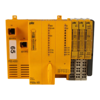
Lists the components included in the product range: base unit and terminators.
Details the product's features, including configurability, outputs, and inputs.
Defines the product's purpose for safety-related interruption of circuits and specific applications.
Lists other documents required for full product understanding and correct usage.
Refers to product modifications and version overview for configurator compatibility.
General overview of safety regulations and compliance.
Emphasizes the need for a safety assessment per Machinery Directive for plant safety.
Defines competent persons and the company's responsibility for employing qualified staff.
Outlines conditions under which warranty and liability claims become invalid.
Advises on proper disposal procedures according to local regulations and mission time.
Lists essential safety requirements for safe operation and system integrity.
Details measures for protecting plants and networks against cyber threats and unauthorized access.
Explains the built-in redundancy, self-monitoring, and output testing for safety.
Describes how inputs/outputs function based on safety circuits configured via the PNOZmulti Configurator.
Refers to a document for calculating maximum reaction times between input and output switching.
Presents a block diagram illustrating the system's internal structure and connections.
Explains how status and error messages are saved in an error stack and accessed.
Details the use of test pulse outputs for detecting shorts between inputs.
Provides guidelines for installing the unit within a control cabinet, including mounting and EMC.
Specifies minimum distances required around the unit for proper heat dissipation and access.
Shows the physical dimensions of the unit with spring-loaded terminals.
Instructions for installing the base unit on a mounting rail, ensuring terminators are in place.
Explains how to connect expansion modules to the base unit using jumpers.
Outlines essential wiring practices, including cable types, protection circuits, and power supply.
Details the procedure for wiring inputs and outputs and connecting the supply voltage.
Step-by-step procedure for loading a project from a chip card onto the base unit.
Instructions for downloading a project from a PC to the base unit using a USB connection.
Emphasizes the importance of performing function tests after configuration changes.
Provides notices and instructions for handling and inserting the chip card safely.
Illustrates a detailed wiring example for dual-channel E-STOP and safety gate.
Explains the meaning of the POWER, RUN, DIAG, FAULT LEDs and their states.
Describes the LC display's four lines and how to navigate through menus.
Explains how to use the rotary knob for menu settings, including extending, retracting, rotating, and pressing.
Provides flowcharts for navigating menu levels when the device is in STOP or RUN mode.
Guides on displaying stored error messages and lists common error messages and their meanings.
Explains how to read the error stack from the LC display or PNOZmulti Configurator.
Details how to manually switch test pulse outputs via the display menu.
Explains how to display device data and operating parameters for the base unit and expansion modules.
States that no maintenance is required during normal operation and advises returning faulty products.
Presents safety characteristic data for logic, inputs, and outputs according to various standards.
Describes interface classes and parameters for input and output compatibility.
Graph showing the relationship between capacitive load and load current for semiconductor outputs.
Graph illustrating the maximum permitted total current for semiconductor outputs.
Graphs showing maximum relative humidity limits during operation and storage.
Lists the main product (PNOZ m B0.1) with its features and order number.
Lists accessories such as terminating plugs, cables, and terminals with their order numbers.
| Number of safety contacts | 2 |
|---|---|
| Number of Auxiliary Contacts | 0 |
| Operating voltage | 24 V DC |
| Supply voltage | 24 V DC |
| Category | 4 |
| Connection type | Screw terminal |
| SIL | 3 |
| PL | e |
| Standards | EN ISO 13849-1 |
| Product type | Safety Relay |