Function description
Operating Manual PNOZ m B0.1
1005720-EN-04
| 14
5 Function description
5.1 Integrated protection mechanisms
The relay meets the following safety requirements:
} The circuit is redundant with built-in self-monitoring.
} The safety device remains effective in the case of a component failure.
} The safety outputs are tested periodically using an off-test.
Please note that the off-test is not carried out when the output is configured as an Output
with reduced fault detection (see online help for the PNOZmulti Configurator).
5.2 Functions
The function of the inputs and outputs on the control system depends on the safety circuit
created using the PNOZmulti Configurator. A chip card is used to download the safety cir-
cuit to the base unit. The base unit has 2 microcontrollers that monitor each other. They
evaluate the input circuits on the base unit and expansion modules and switch the outputs
on the base unit and expansion modules accordingly.
The LEDs on the base unit and expansion modules indicate the status of the configurable
control system PNOZmulti.
The online help on the PNOZmulti Configurator contains descriptions of the operating
modes and all the functions of the control system, plus connection examples.
5.3 System reaction time
Calculation of the maximum reaction time between an input switching off and a linked out-
put in the system switching off is described in the document "PNOZmulti System Expan-
sion".
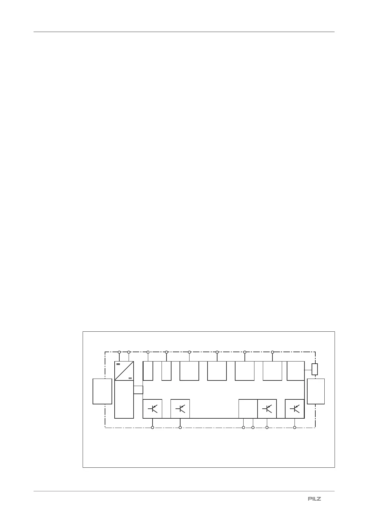
5.4 Block diagram
Power
A1 A2
...
...
...
...
...
Config
I/O
IM0
...
...
IM3 IM16
...
...
IM19
T0M20
T3M23
Config
I/O
Config
I/O
Config
I/O
0 V 24 V
Output
Supply
...
O0 O3
USB
Expansion
module
Int
erface
Expansion
module
Interface
I4
Input
I15
Input

 Loading...