9
Operating Manual: PSS SB ACTIVE JUNCTION BASIS
SafetyBUS p interfaces
SafetyBUS p main branch
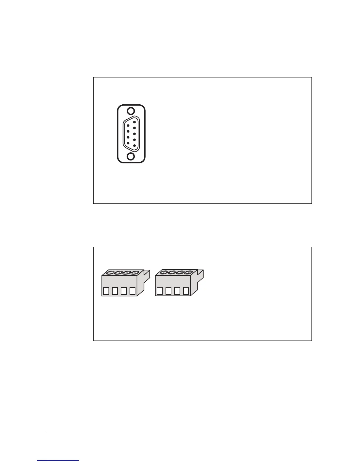
Connection to the SafetyBUS p main branch is via a male 9-pin D-Sub connector.
Fig. 4: Configuration of the interface to the SafetyBUS p main branch
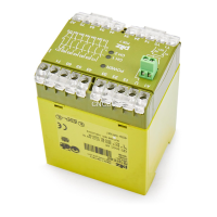
SafetyBUS p sub branches
Connection to the SafetyBUS p sub branches is via 4-pin screw connectors.
1: n.c.
2: CAN_L (brown)
3: CAN_GND (white)
4: n.c.
5: CAN_SHLD
6: n.c.
7: CAN_H (green)
8: Supply voltage for fibre-optic couplers
from Pilz
9: n.c.
n.c. = not connected
1
9
5
6
Male 9-pin D-Sub connector
9-pin
1234
X1
1234
X2
Fig. 5: Configuration of the interface to the SafetyBUS p sub branches
4-pin screw connectors
(X1/X2)
1: CAN_L (brown)
2: GND (white)
(CAN_GND and VCC_GND)
3: CAN_H (green)
4: VCC (red)
(carried supply voltage 24 V)