Captain 8
39
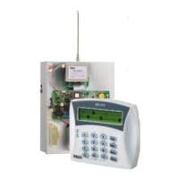
2. Connect the +/- wires to the control panel's (+V) and (-) terminals.
3. Connect the Blue wire to the control panel's AUDIO IN terminal.
4. The Yellow and white wires are not in use.
5. See the programming instructions of the Hunter-Pro Series from page 25.
Diagram 39. VU-20N/U single message connection diagrams
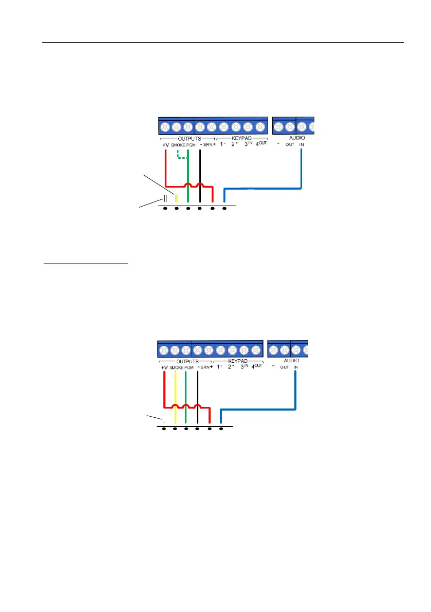
Two message wiring
1. Connect the Green wire (M1) to either the control panel's PGM or the SMOKE outputs, or to
the I/O8-N output see the next diagram.
2. Connect the Yellow wire (M2) to a different output.
3. Connect the +/- wires to the control panel's zones voltage.
4. Connect the Blue wire to the control panel's AUDIO IN terminal.
Diagram 40. VU-20N/U two message connection diagrams
Control panel
VU-20U
YELLOW
BLUE
RED
BLACK
GREEN
M1
M2
GND
+12V
Audio
CONT
WHITE
Control panel
VU-20U
YELLOW
BLUE
RED
BLACK
GREEN
M1
M2
GND
+12V
Audio
CONT
WHITE
 Loading...