Hunter-Pro Series Captain 8 - Installation Guide
38
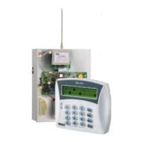
Diagram 37. Telephone Wiring
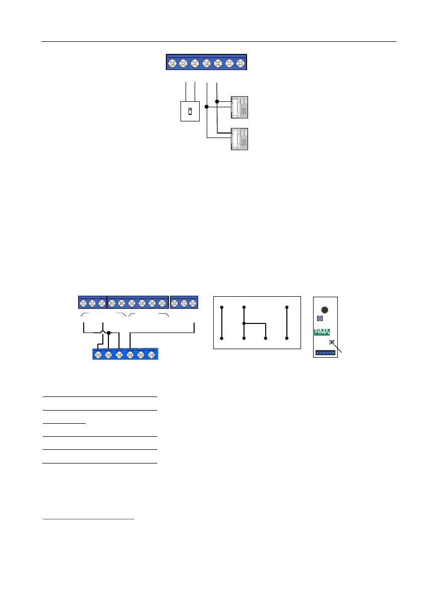
2.3.5. MIC-200 Microphone
Connect the MIC-200 according to the following diagram and table:
1. In the “Zone Responses” menu, set "M- Activate Audio" to '+', in every zone type that should
trigger the microphone in alarm see section 5.2, on page 48.
2. In the "Output configuration" menu, set the polarity of triggering output to "-" see
section 10.4, on page 67.
3. In the "Communication Options" menu, set "Voice Unit" to "+" see section 6.4, on page 51.
4. The PGM/SMOKE outputs should be triggered by the "Audio Control" output type see
section 10.2, starting page 65.
Diagram 38. MIC-200 Wiring
2.3.6. VU-20N/U Voice message module
The VU-20U is a voice message recorder, which enables to play up to 2 messages via the phone,
when the alarm is set off.
Single message wiring
To use the VU-20U for a single message:
1. Connect the Green wire (M1) to either the control panel's PGM or the SMOKE outputs, or to
the I/O8-N output see the next diagram.
Z1 Z2 Z3
Z4 Z5 Z6
Z
O
N
E
S
+V
SMOKE PGM
SRN
OUTPUTS
-
1
KEYPAD
OUT LINE
TELEPHONE
SET
-
AUDIO
IN
F
2
Z7 Z8
2 3 4
+
IN
OUT
-
-
-
+
Telephone
line-in
Telephone
set/Fax
Control panel
MIC-200
(-)12(+) CON.OUT TAMP
Tamper
MIC-200
(-)12(+) CON OUT TAMP
+V
SMOKE PGM
SRN
-
1
KEYPAD
OUT
-
AUDIO
IN
2 3 4
+
IN
OUT
-
+
OUTPUTS
(-)
(+)
AUD IN
PGM
(+)
CON OUT
 Loading...