EasyManua.ls Logo

Pioneer HTV-C1 User Manual

Pioneer HTV-C1
52 pages
To Next Page IconTo Next Page
Page #1 background imageLoading...
Page #1 background image
ORDER NO.
PIONEER ELECTRONIC CORPORATION 4-1, Meguro 1-Chome, Meguro-ku, Tokyo 153-8654, Japan
PIONEER ELECTRONICS SERVICE, INC. P.O. Box 1760, Long Beach, CA 90801-1760, U.S.A.
PIONEER ELECTRONIC (EUROPE) N.V. Haven 1087, Keetberglaan 1, 9120 Melsele, Belgium
PIONEER ELECTRONICS ASIACENTRE PTE. LTD. 253 Alexandra Road, #04-01, Singapore 159936
PIONEER ELECTRONIC CORPORATION 1998
HTV-C1
DDXJ AC110–127V/220–230V/240V With the voltage selector
ADXJ AC power supplied from power trans-
former's secondary of other system component
This product is a system component. This product does not function properly when independent;
to avoid malfunctions, be sure to connect it to the prescribed system component, otherwise
damage may result. The Powered Subwoofer HTV-SW1 is a part of the Hometheater System HTV-
1.
POWERED SUBWOOFER
RRV2060
T–ZZR NOV. 1998 Printed in Japan
HTV-SW1
1. SAFETY INFORMATION.................................... 2
2. EXPLODED VIEWS AND PARTS LIST ............. 3
3. SCHEMATIC DIAGRAM................................... 10
4. PCB CONNECTION DIAGRAM ....................... 24
5. PCB PARTS LIST ............................................. 36
6. ADJUSTMENT.................................................. 39
7.GENERAL INFORMATION ............................... 40
7.1 PARTS ........................................................ 40
CONTENTS
7.1.1 IC ........................................................... 40
7.1.2 DISPLAY................................................ 42
7.2 DIAGNOSIS ................................................ 43
7.3 TEST MODE(HTV-C1) ............................... 45
7.4 INDEPENDENT OPERATION DIAGNOSIS46
7.5 BACKUP FUNCTION (HTV-C1)................. 47
7.6 BLOCK DIAGRAM...................................... 48
8.PANEL FACILITIES AND SPECIFICATIONS ..... 50
THIS MANUAL IS APPLICABLE TO THE FOLLOWING MODEL
(
S
)
AND TYPE
(
S
)
.
CONTROL CENTER
• HTV-SW1
• HTV-C1
SURROUND MODE
STANDBY/ON
DISPLAY INPUT
VOLUME
Hometheater System Control Center
HTV-1 HTV-C1 (this service manual)
(service manual RRV2063)
Powered Subwoofer
HTV-SW1 (this service manual)
The voltage can be converted by
the following method.
Model
HTV-SW1 HTV-C1
Type Power Requirement
Power Amp
HTV-A1 (this service manual)
w
w
w
.
x
i
a
o
y
u
1
6
3
.
c
o
m
Q
Q
3
7
6
3
1
5
1
5
0
9
9
2
8
9
4
2
9
8
T
E
L
1
3
9
4
2
2
9
6
5
1
3
9
9
2
8
9
4
2
9
8
0
5
1
5
1
3
6
7
3
Q
Q
TEL 13942296513 QQ 376315150 892498299
http://www.xiaoyu163.com
Question and Answer IconNeed help?

Do you have a question about the Pioneer HTV-C1 and is the answer not in the manual?

Pioneer HTV-C1 Specifications

General IconGeneral
BrandPioneer
ModelHTV-C1
CategorySubwoofer
LanguageEnglish

Summary

Pioneer HTV-SW1 HTV-C1 Service Manual

Overview of HTV-SW1 and HTV-C1 Models

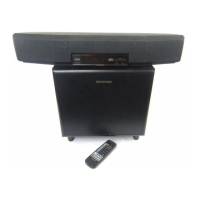
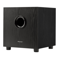
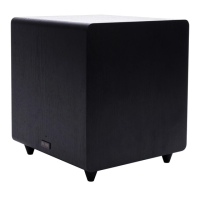
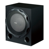
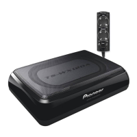
Identifies the Powered Subwoofer HTV-SW1 and Control Center HTV-C1 models.

Applicable Models and Voltage Conversion

Details models HTV-SW1 and HTV-C1 and voltage conversion methods.

Safety Information and Precautions

General Safety Warnings

General warnings for qualified technicians regarding safe repair practices.

Product Safety Notices

Highlights safety-related characteristics of electrical components and replacement parts.

Leakage Current Check Procedure

Procedure to measure leakage current to earth ground for safety.

Exploded Views and Parts Lists

HTV-SW1 Packing Details

Exploded view and parts list for the HTV-SW1 packing.

HTV-SW1 Exterior and Cabinet Parts

Exploded view of the HTV-SW1 exterior and list of cabinet parts.

HTV-A1 Power Amp Exterior Parts

Exploded view of the HTV-A1 power amp exterior and list of parts.

HTV-A1 Power Amp Exterior Parts List

Detailed list of parts for the HTV-A1 power amp exterior.

HTV-C1 Packing Details

Exploded view and parts list for the HTV-C1 packing.

HTV-C1 Main Section Exploded View

Exploded view of the HTV-C1 main section, showing component layout.

HTV-C1 Main Section Parts List

Detailed list of parts for the HTV-C1 main section.

Schematic Diagrams

HTV-A1 Overall Connections Schematic

Overall connection diagram for the HTV-A1 amplifier section.

HTV-A1 Key Assembly Schematics

Schematics for key HTV-A1 assemblies like AFPS, PAMP, JACK.

HTV-A1 AFPS Assembly Schematic

Schematic diagram for the AFPS assembly of the HTV-A1.

HTV-A1 AFPS Assembly Schematic (Cont.)

Continuation of the schematic diagram for the AFPS assembly.

HTV-A1 PAMP Assembly Schematic

Schematic diagram for the PAMP assembly of the HTV-A1.

HTV-A1 PAMP Assembly Schematic (Cont.)

Continuation of the schematic diagram for the PAMP assembly.

HTV-A1 Jack Assembly Schematic

Schematic diagram for the Jack Assembly of the HTV-A1.

Waveform Diagrams

HTV-A1 Waveform Analysis

Waveforms for HTV-A1 circuit points, used for analysis.

HTV-C1 Waveform Analysis

Waveforms for HTV-C1 circuit points, used for analysis.

Schematic Diagrams - HTV-C1

HTV-C1 Overall Connections Schematic

Schematic showing overall connections for the HTV-C1 control center.

HTV-C1 Main Assy Voltage Measurements

Voltages of the Main Assy IC3001 (CXD2724Q) in different modes.

HTV-C1 Main, Input Lev., and Terminal Assy Schematics

Schematics for HTV-C1 Main, Input Lev., and Terminal assemblies.

HTV-C1 Main, Input Lev., and Terminal Assy Schematics (Cont.)

Continuation of schematics for HTV-C1 Main, Input Lev., and Terminal assemblies.

HTV-C1 Display Assembly Schematic

Schematic diagram for the HTV-C1 Display Assembly.

HTV-C1 Display Assembly Schematic (Cont.)

Continuation of the schematic diagram for the HTV-C1 Display Assembly.

PCB Connection Diagrams

HTV-A1 AFPS, PT SEC, PT PRI PCB Layouts

PCB connection diagrams for HTV-A1 AFPS, PT SEC, and PT PRI assemblies.

HTV-A1 AFPS PCB Layout (Side A/B)

PCB layout for the HTV-A1 AFPS assembly, showing both sides.

HTV-A1 AFPS PCB Layout (Side A/B) (Cont.)

Continuation of the PCB layout for the HTV-A1 AFPS assembly.

HTV-A1 PT SEC & PT PRI PCB Layouts

PCB layouts for HTV-A1 PT SEC and PT PRI assemblies.

HTV-A1 Standby PT & PW Switch PCB Layouts

PCB connection diagrams for HTV-A1 Standby PT and PW Switch assemblies.

HTV-A1 Jack Assembly PCB Layout

PCB connection diagram for the HTV-A1 Jack Assembly.

HTV-A1 PAMP Assembly PCB Layout

PCB connection diagram for the HTV-A1 PAMP Assembly.

HTV-A1 PAMP Assembly PCB Layout (Cont.)

Continuation of the PCB connection diagram for the HTV-A1 PAMP Assembly.

PCB Connection Diagrams - HTV-C1

HTV-C1 Main Assy PCB Layout

PCB layout for the HTV-C1 Main Assembly.

HTV-C1 Main Assy PCB Layout (Cont.)

Continuation of the PCB layout for the HTV-C1 Main Assembly.

HTV-C1 Input Lev., Terminal, Display PCB Layouts

PCB layouts for HTV-C1 Input Lev., Terminal, and Display assemblies.

HTV-C1 Input Lev., Terminal, Display PCB Layouts (Cont.)

Continuation of PCB layouts for HTV-C1 Input Lev., Terminal, and Display assemblies.

PCB Parts Lists

HTV-A1 PCB Assemblies and Components

Lists PCB assemblies and semiconductor/capacitor/resistor components for HTV-A1.

HTV-A1 Components and Other Parts

Lists semiconductors, capacitors, coils, resistors, and other parts for HTV-A1.

HTV-C1 PCB Assemblies and Components

Lists PCB assemblies and semiconductor/capacitor/resistor components for HTV-C1.

HTV-C1 Components and Other Parts

Lists semiconductors, coils, switches, capacitors, resistors, and other parts for HTV-C1.

General Information on Components

IC Component Information (BU2092F, M62419FP)

Details IC components BU2092F and M62419FP, including pin functions and block diagrams.

IC Component Pin Functions (M62419FP)

Detailed pin function descriptions for the M62419FP IC.

Display Component Information (AAV7052)

Information on the AAV7052 display component, including pin assignment and grid/anode connections.

Diagnosis and Disassembly Procedures

HTV-A1 Disassembly Guide

Step-by-step guide for disassembling the HTV-A1 unit, including bonnet case and AFPS assembly.

HTV-A1 Independent Operation Diagnosis

Method for diagnosing HTV-A1 operation independently using short circuits and signal inputs.

Test Modes and Standby Function

HTV-C1 Test Mode Entry and Operation

Procedures for entering, operating, and canceling test modes on the HTV-C1.

Automatic Standby Function Confirmation

Procedure to confirm the automatic standby function of the unit.

Diagnosis Methods

HTV-C1 Independent Operation Diagnosis

Method for diagnosing HTV-C1 operation independently using AC voltage and signal gain.

Backup Functionality

HTV-C1 Backup Function Settings

Details on memory settings retained by backup power supply and factory settings.

Block Diagrams

HTV-C1 Control Center Block Diagram

Block diagram illustrating the HTV-C1 Control Center's signal paths and components.

HTV-A1 Amplifier Block Diagram

Block diagram illustrating the HTV-A1 Amplifier's signal paths and components.

Panel Facilities and Specifications

HTV-C1 Control Center Panel Layout

Description and layout of the HTV-C1 control center panel, including buttons and indicators.

Remote Control Unit Operation

Details on the operation of the remote control unit for both Australian and non-Australian models.

System Specifications

HTV-1 Amplifier and Speaker Specifications

Technical specifications for the amplifier and speaker sections of the HTV-1 system.

HTV-1 Miscellaneous and Furnished Parts

Miscellaneous specifications, furnished parts, and accessories for the HTV-1 system.

Related product manuals