Do you have a question about the Pioneer PDP-6010FD and is the answer not in the manual?
Guidelines for using lead-free solder and proper soldering techniques for environmental protection and repair quality.
Identification of hazardous high voltage areas and necessary precautions to prevent electric shock.
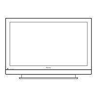
List of items included with the plasma display unit for setup and use.
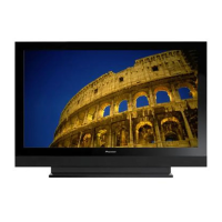
Technical details and performance characteristics of the PDP-6010FD model.
Overview of the physical connectors and controls located on the display panel.
Essential checks to ensure product quality and safety after repairs are completed.
Concise guide to common service procedures, diagnosis, and settings.
Diagram showing the location of main printed circuit boards within the unit.
Schematic illustrating the interconnectivity of major components and signal paths.
High-level functional overview of the system's main blocks and data flow.
Detailed block diagram of the power supply unit and its voltage outputs.
Information on LED indicators and their meaning for diagnosing power supply status.
Step-by-step guide for troubleshooting common unit failures.
Analysis of power-down issues, including block diagrams and failure causes.
Analysis of shutdown issues, including block diagrams and failure causes.
Introduction to the service factory mode, its purpose, and transition chart.
Details on how functions behave and are set when entering the service factory mode.
Mapping of remote control keys to functions within the service factory mode.
Step-by-step visual guide for safely disassembling the unit.
Procedures for disassembling specific assemblies like the speaker system.
Guidance on necessary adjustments after replacing major internal assemblies.
Procedures for backing up and restoring essential adjustment data from the EEPROM.
Specific procedures for adjusting the unit after replacing the service panel assembly.
Comprehensive table of available RS-232C commands, their functions, and usage.
In-depth explanation of specific RS-232C commands and their parameters.
List of parts included in the product packaging.
Diagram showing the location of parts on the rear of the unit.
Detailed parts list and diagrams for the main chassis section.
| Screen Size | 60 inches |
|---|---|
| Display Type | Plasma |
| Aspect Ratio | 16:9 |
| Contrast Ratio | 30, 000:1 |
| Weight | 60.6 kg |
| Resolution | 1920 x 1080 (1080p) |
| Input Ports | HDMI, Component, Composite, S-Video |