Do you have a question about the Pioneer PRO-141FD and is the answer not in the manual?
Important precautions to be observed during service operations for safety.
List of accessories included with the product models.
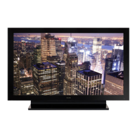
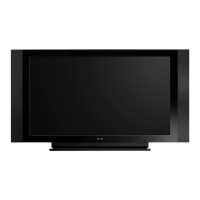
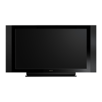
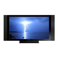
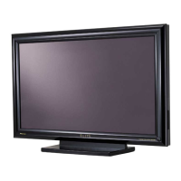
Detailed technical specifications for each model.
Description of front and rear panel terminals and controls.
Recommended checks to ensure product quality after repair.
Quick reference for service notes, diagnosis, and settings.
Identification and location of Printed Circuit Boards.
Overall wiring diagram of the system.
Continuation of the overall wiring diagram.
Overall block diagram of the system.
Continuation of the overall block diagram.
Detailed block diagram of the power supply unit.
Block diagram of the 60F X Drive Assembly.
Block diagrams for Y Drive and Scan Assemblies.
Power supply block overview for drive and scan assemblies.
Block diagrams for Address L and S Assemblies.
Block diagram of the 60F Digital Assembly.
Power supply block for Main and I/O Assys.
Block diagram for LED and IR Assemblies.
LED display patterns indicating power supply status.
Flowcharts for analyzing unit and component failures.
Block diagram and diagnosis of power-down signals.
Block diagram and diagnosis of shutdown signals.
Information on symptoms that do not indicate failure.
Explanation of panel drive-power ON/OFF function.
Overview of RS-232C and IP commands for service.
Comprehensive list of RS-232C and IP commands.
Detailed explanation of specific RS-232C and IP commands.
Information on controlling the PDP via IP network.
Overview of the service factory mode and transition diagrams.
Detailed breakdown of the factory menu options.
Step-by-step guide for disassembling the unit.
Detailed disassembly procedures for major components.
Required adjustments after replacing key assemblies.
Procedure for backing up EEPROM data from the Digital Assy.
Methods for clearing various logs and history data.
Specific adjustments needed after replacing the service panel assembly.
Adjustments required after replacing drive assemblies.
Step-by-step guide for updating the firmware.
Exploded view and parts list for packing of PRO-141FD/KU/CBXC.
Exploded view and parts list for packing of KRP-600M/KUCXC.
Exploded view and parts list for packing of KRP-600M/YVPSLFTD.
Exploded view and parts list for packing of KRP-600M/TYVXK5.
Exploded view of the rear section of the unit.
Exploded view of the front section of the unit.
Exploded view of the chassis section.
Continuation of the chassis section exploded view.
Exploded view of the panel chassis section.
Exploded view of the Multibase section.
Exploded view of the PDP Service Assembly.
| Screen Size | 60 inches |
|---|---|
| Resolution | 1920 x 1080 |
| Display Technology | Plasma |
| Panel Type | Plasma |
| HDMI Inputs | 4 |
| Aspect Ratio | 16:9 |
| Connectivity | HDMI, Component, Composite, S-Video |