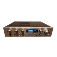
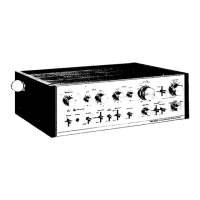
STEREO
AM
PLIFIER
Stu4lOm
r
This additional
service
manual
is applicable
to the HE
and HB
types.
I
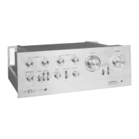
The
basic
performance
of the
SA-410/HE and HB
types
are the
same as
theSA-41o/KU
type.
please
refer
to the
SA-41O/KU
service manual
<ART-480)
with
exception
of this
supplement.
1.
SPECIFICATIONS
The
specifications
for
SA-41O/HE
and HB
types
are
ing section;
M
iscellaneous
Power
Requirements
HE type
220V,240V,
50l60Hz
220V,240V,
50l60HzH B typc
Power
Consumption
HE,HBtypes.
.....140W
Weight
(without
package)
5dg
(1
1 lb)
the
same as the
SA-410/KU
type except for
follow-
Hum and Noise
(DlN
continuous
power/5OmW)
PHONO.
.....67d8161d8
TUNER,
AUX, TAPE PLAY
.
.83d8/63d8
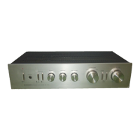
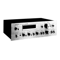
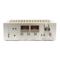
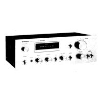
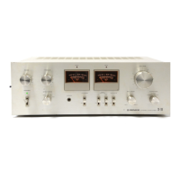
MODEL
SA-410
COMES
IN FIVE
VERSIONS
DISTINGUISHED
AS
FOLLOWS:
Type
Voltage
Remarks
KU
12OV
only
U.S.A.
model
S
110V, 120V,22OV
and
240V
(Switchable)
General
export
model
HE
22AY and
24OY Europe
model
HB 22OV and
24OV
United
Kingdom
model
YP
24OV
onlv
Australia model
PIONEEFI
FLECTFICINIC
CCIFIPTOF|ATICTN 41.Me!rL,.o i
cj,,-,r,e.Mea,,.oki,. roky.r ls3.Jarran
u.8.
PICTNEEFI
ELECTFIOINICEI
COCIPCICIATION EJ5
(fxt(r.(i
fJ, we. Moorract,,e
New Je'.s.rv
O7074. U
S
A
rlO|\lEEFl
ELECTFIONIC
(€UCrcFEt
N.\/. L(rLr,agerr Haw.j.,
g
2O3O A|r-we.p.
Eles,r,,rr
PIO
IEEFI
ELECTFIONICg
ALTATE|ALIA
PTY.
LlCt.
17Ff 1E'4
E!.r!rncl.r'
v
Hr)a.1.
Bi
eres(kr wict.,)r.,a
:Jl95.
A(,sL.ai,.l
..ART
530-0r'.
y
o MAR.
1980
Printed
in
lapan