53
XR-A6800, XR-A4800
Step
No.
Adjustment
Title
FM SG (1kHz, ± 75kHz dev.)
Reception
Frequency
Display
Adjustment
Location
Specifications
Frequency
(MHz)
Level
(dBµV)
1
Front End
Sensitivity
106 0 to 30 106MHz
L6104
L6105
L6102
T6101
Adjust so that the DC voltage between the
IC6201 - pin 20 and GND becomes at maximum
level.
2 Stereo Distortion
98
(ON STEREO)
80 98MHz T6101
Minimize the distortion with 1/8 rotation of the
core.
3
TUNED IND.
Lighting Level
98 18 ± 2 98MHz VR6201
Adjust so that the indicator of TUNED IND.
starts to light up.
Step
No.
Adjustment
Title
AM SG (400Hz, 30% Mod.)
Reception
Frequency
Display
Adjustment
Location
Specifications
Frequency
(kHz)
Level
(dBµV/m)
1
Front End
Sensitivity
999 (∗1) 35 to 45 999kHz (∗1)
T6201
Adjust so that the DC voltage between the
IC6201 - pin 20 and GND becomes at maximum
level.
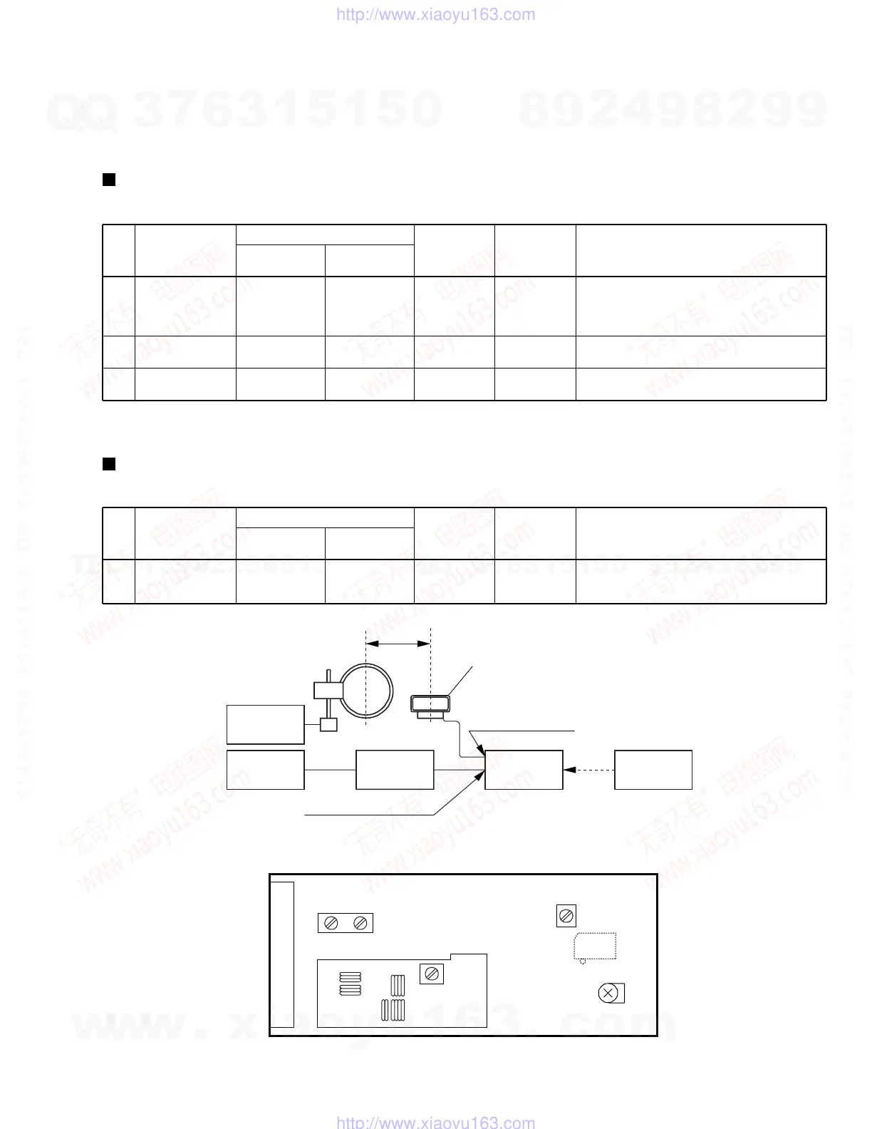
6. ADJUSTMENT
6.1 TUNER SECTION
FM Tuner Section
• Set the mode selector to FM BAND.
• Connect the wiring as shown in Fig. 1.
AM Tuner Section
• Set the mode selector to AM BAND.
• Connect the wiring as shown in Fig. 1.
Note:
Before adjusting, make sure there is no gap between L6101 and L6102 as well as between L6103 and L6104. If there is a gap between them,
bring them into contact with each other first, and then make adjustments.
Note (∗1) : For the area using 10kHz step, frequency should be 1000kHz.
AM SG
MPX SG FM SG
PRODUCT
DC
Voltmeter
FM75Ω antenna terminal
AM antenna terminal
60cm
Center
Center
Loop antenna
Fig.1 AM and FM Adjustment Wiring Diagram
FM/AM TUNER MODULE
AXX7042
L6101
L6102
L6103
L6104
L6105
T6101
T6201
VR6201
AM
antenna
terminal
FM
antenna
terminal
YELLOW BLACK
Fi
.2 Adjustment Point
IC6201
Pin 20
w
w
w
.
x
i
a
o
y
u
1
6
3
.
c
o
m
Q
Q
3
7
6
3
1
5
1
5
0
9
9
2
8
9
4
2
9
8
T
E
L
1
3
9
4
2
2
9
6
5
1
3
9
9
2
8
9
4
2
9
8
0
5
1
5
1
3
6
7
3
Q
Q
TEL 13942296513 QQ 376315150 892498299
TEL 13942296513 QQ 376315150 892498299
http://www.xiaoyu163.com
http://www.xiaoyu163.com

 Loading...