EasyManua.ls Logo

Pioneer XV-DV590K User Manual

Pioneer XV-DV590K
101 pages
To Next Page IconTo Next Page
Page #1 background imageLoading...
Page #1 background image
ORDER NO.
PIONEER CORPORATION 4-1, Meguro 1-chome, Meguro-ku, Tokyo 153-8654, Japan
PIONEER ELECTRONICS (USA) INC. P.O. Box 1760, Long Beach, CA 90801-1760, U.S.A.
PIONEER EUROPE NV Haven 1087, Keetberglaan 1, 9120 Melsele, Belgium
PIONEER ELECTRONICS ASIACENTRE PTE. LTD. 253 Alexandra Road, #04-01, Singapore 159936
PIONEER CORPORATION
2009
2009 Printed in Japan
MAIN
USB
SUBMIC
PHONES
XV-DV282AP
RRV3936
DVD/CD RECEIVER
XV-DV282AP
XV-DV181
XV-DV180
XV-DV585K
XV-DV590K
THIS MANUAL IS APPLICABLE TO THE FOLLOWING MODEL(S) AND TYPE(S).
Model Type Power Requirement Region No. Remarks
XV-DV282AP LXJ AC 220 V to 240 V 3
XV-DV181 LXJ AC 220 V to 240 V 3
XV-DV180 LXJ AC 220 V to 240 V 3
XV-DV585K SXJ5 AC 220 V to 240 V 5
XV-DV590K SXJ5 AC 220 V to 240 V 5
For details, refer to "Important Check Points for good servicing".
T- Z Z K M AY

Table of Contents

Question and Answer IconNeed help?

Do you have a question about the Pioneer XV-DV590K and is the answer not in the manual?

Pioneer XV-DV590K Specifications

General IconGeneral
BrandPioneer
ModelXV-DV590K
CategoryReceiver
LanguageEnglish

Summary

SAFETY INFORMATION

LABEL CHECK

Provides information on product labels and warnings related to laser emission.

LASER DIODE CHARACTERISTICS

Details laser diode specifications, including maximum output power and wavelength.

1. SERVICE PRECAUTIONS

1.1 NOTES ON SOLDERING

Guidelines for using lead-free solder and appropriate soldering irons for environmental protection.

1.2 CAUTION

Important warnings regarding BTL drive, speaker terminals, and chassis connections.

2. SPECIFICATIONS

2.1 SPECIFICATIONS, DISC/CONTENT FORMAT AND ACCESSORIES

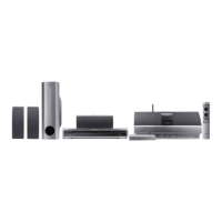
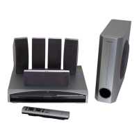
Details amplifier, tuner, disc compatibility, and included accessories.

Disc/content format playback compatibility

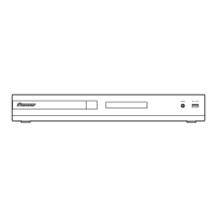
Information on playable disc types and formats, featuring compatibility logos.

3. BASIC ITEMS FOR SERVICE

3.1 CHECK POINTS AFTER SERVICING

Recommended checks to ensure proper product quality after service, including firmware and appearance.

3.2 PCB LOCATIONS

Shows the physical placement of various PCBs within the unit, with notes on part importance.

4. BLOCK DIAGRAM

4.1 OVERALL WIRING CONNECTION DIAGRAM

Illustrates the interconnections between major components and their respective assemblies.

4.2 OVERALL BLOCK DIAGRAM

Shows the system architecture and signal flow between main blocks.

5. DIAGNOSIS

5.1 METHOD FOR DIAGNOSING DEGRADATION OF THE LDS ON THE PICKUP

Steps to diagnose laser diode degradation using voltage measurements on the pickup PCB.

5.2 DVD TROUBLE SHOOTING

Common symptoms and diagnostic steps for DVD playback issues, referencing specific ICs.

6. SERVICE MODE

6.1 TEST MODE

How to enter and operate the unit in test mode for diagnostics using the remote control.

6.2 DISPLAY SPECIFICATION OF THE TEST MODE

Explains the format and meaning of information displayed in test mode, including address and status.

7. DISASSEMBLY

[1] Bonnet, Tray Panel

Step-by-step instructions for removing the bonnet and tray panel, including power sequence.

[2] Front Panel Section

Procedure for removing the front panel assembly, with notes on screw usage.

8. EACH SETTING AND ADJUSTMENT

8.1 ID NUMBER AND ID DATA SETTING

Procedures for setting the player's ID number and data, required for CPRM and HDCP.

9. EXPLODED VIEWS AND PARTS LIST

9.1 PACKING SECTION

Exploded view and parts list for the packing and accessories included with the unit.

9.2 EXTERIOR SECTION

Exploded view showing exterior parts and their locations within the unit's chassis.

10. SCHEMATIC DIAGRAM

10.1 09 DVDM ASSY (1/2)

Schematic diagram for the 09 DVDM Assy, covering components and connections.

10.2 09 DVDM ASSY (2/2)

Schematic diagram for the 09 DVDM Assy, detailing remaining components and connections.

11. PCB CONNECTION DIAGRAM

11.1 09 DVDM and RHTS USB ASSYS

PCB connection diagrams showing component placement on the 09 DVDM and RHTS USB assemblies.

11.2 RHTS SYSMAIN ASSY

PCB connection diagrams illustrating the RHTS SYSMAIN Assy layout and connector pinouts.

12. PCB PARTS LIST

LIST OF ASSEMBLIES

Lists the part numbers for various assemblies like DVDM, SYSMAIN, D-AMP, and DISPLAY.

Related product manuals