
C
Crystal FloresJul 29, 2025
What does '96k' mean on my Pioneer XV-EV1000?
- BbeckerpatriciaJul 29, 2025
The '96k' indicator on your Pioneer Receiver appears when the audio source is either 88.2 kHz or 96 kHz PCM.
What does '96k' mean on my Pioneer XV-EV1000?
The '96k' indicator on your Pioneer Receiver appears when the audio source is either 88.2 kHz or 96 kHz PCM.
Details about laser diode power and wavelength for DVD and CD.
Mentions checking labels on the product, specifically the CLASS 1 LASER PRODUCT label.
Procedures for safe repair, using specified parts, and avoiding modifications.
Procedures for maintaining product performance through adjustments.
Details continuous power output and power consumption specifications.
Specifications for digital audio characteristics, response, and distortion.
Details systems, heads, motor, and tape types for the cassette deck.
Lists logos indicating compatible disc types like DVD-Video, DVD-R, CD-R.
Shows an exploded view of the packing and lists parts included in the packaging.
Details differences in parts between XV-EV1000 and XV-EV700 models.
Details differences in front panel parts between XV-EV1000 and XV-EV700 models.
Lists all parts for the Traverse Mechanism Assy-S.
Lists all parts for the Deck Mechanism Assy.
High-level overview of the system's functional blocks and connections.
Shows PCB layout and connection points for the LOAB Assy.
Lists main PCB assemblies and their part numbers for models.
Details part differences between models for specific assemblies.
Lists miscellaneous parts for the LOAB Assy.
Lists miscellaneous ICs, transistors, diodes, etc. for the DVDM Assy.
Lists resistor part numbers and their locations.
Lists capacitor part numbers and their locations.
Lists capacitor part numbers and their locations.
Lists specific parts and their part numbers for the IFAF Assy.
Lists ICs, transistors, diodes, etc. for the AMP ASSY.
Lists resistor part numbers and their locations.
Lists capacitor part numbers and their locations.
Lists capacitor part numbers and their locations.
Lists capacitor part numbers and their locations.
Lists capacitor part numbers and their locations.
Lists capacitor part numbers and their locations.
Lists miscellaneous ICs, transistors, diodes, coils, and resistors for the DSP Assy.
Lists capacitor part numbers and their locations.
Lists miscellaneous ICs, switches, and resistors for the KEY Assy.
Lists resistor part numbers and their locations.
Lists capacitor part numbers and their locations.
Lists miscellaneous ICs, transistors, diodes, coils, jacks, and resistors.
Lists resistor part numbers and their locations.
Lists capacitor part numbers and their locations.
Lists resistor part numbers and their locations.
Lists resistor part numbers and their locations.
Lists capacitor part numbers and their locations.
Lists miscellaneous parts for the TRADE Assy.
Covers adjustments for the deck mechanism.
Specifies conditions and tools for deck section adjustments.
Procedures for tape speed, head azimuth, and playback level adjustments.
Procedures for recording bias and recording level adjustments.
Identifies adjustment items and their physical locations on the mechanism.
Lists mechanism and electrical adjustments required for the DVD section.
Shows diagrams of adjustment points and cautions for mechanism adjustments.
Step-by-step instructions for adjusting pickup assembly height.
Information related to system diagnosis.
Explains how to enter and use the test mode for diagnosis.
Explains how the traced address is displayed, including DVD and CD ID indications.
Explains the display of remote control unit codes, including double codes.
Explains the display of main unit keycodes.
Explains the display for tracking status (ON/OFF).
Explains the display for spindle status (CLV/OFF).
Explains the display values for mechanism loading positions.
Explains the display values for slider position (Side Switch ON/OFF).
Explains the display for video systems (NTSC, PAL, AUTO).
Explains the output settings for scart terminals (VIDEO, S-VIDEO, RGB).
Explains the display of disc types loaded.
Explains the display of region settings, [1] to [6].
Explains the display of destination codes and their meaning.
Explains the display of flash ROM version and size.
Details how to enter service mode and display error rates.
Explains how to calculate and interpret average error rates for DVDs and CDs.
Explains how to display model information like region and versions.
Details the procedure for confirming region settings and potential error messages.
How destination is indicated based on FL controller model info.
Indicates the region number.
Displays the product's part number.
Indicates the ROM version.
Displays the flash memory size.
Shows the version of the FL controller.
Shows the chip version.
Displays the code for the remote control.
Displays the key code for the main unit.
Explains the display during service mode including ID Address and error rate.
Details the calculation and interpretation of average error rates for DVDs and CDs.
Describes the display of EDC/ID error history.
Lists conditions for service test mode, like VDET and XPROTECT neglect.
Instructions on connecting STEST port and AC power to enter service test mode.
Instructions on quitting service test mode and conditions for data clearing.
Explains FL display indications based on power status during service test mode.
Describes how operations in service test mode are similar to normal mode but with different FL display indications.
Steps to enter DSP error message mode using the remote control.
Steps to exit DSP error message mode and return to normal test mode.
Explains the meaning of characters displayed for DSP errors.
Shows example displays of DSP errors like ERR_0, ERR_1, etc.
Procedure to diagnose laser diode degradation by measuring voltage across resistors.
Lists symptoms and diagnostic steps for DVD playback issues.
Provides specific checks for identified symptoms.
Suggests potentially defective parts for each symptom.
Lists symptoms and diagnostic steps for DVD playback issues.
Provides specific checks for identified symptoms.
Suggests potentially defective parts for each symptom.
Lists symptoms related to EEP ROM failure.
Lists symptoms related to Flash ROM failure.
Lists symptoms related to DVD IC failure.
Lists symptoms related to SDRAM failure.
Important note regarding ID setting for DVD-RW playback and CPRM.
Notes on entering ID numbers and confirmation mode.
Lists required jigs and instruments for ID setting.
Step-by-step guide for entering the ID number.
Explains when an already set ID number is displayed.
Explains the "No ID Num!" message when no ID is set.
Explains the "Rom Write OK!" message and how to exit.
Explains the "Disc Error!" message and disc ejection.
Explains the "NO ID DATA" message after ID number change.
Lists common DSP errors (ERR_0 to ERR_4) and their assumed causes.
Explains the INFO_0 indication and its potential cause.
Explains the INFO_1 indication and its potential cause.
Notes limited DSP function when this information is displayed.
Provides additional notes on DSP error display and analog audio output issues.
Shows connection details for the IFAF Assy.
Shows connection details for the DSP Assy.
Step-by-step instructions for removing the bonnet and tray.
Procedure to open the tray using a tweezer if power is off.
Notes on safety and required service jigs for PCB diagnosis.
Instructions for removing front panel, grounding screw, and cable hooks.
Notes on connecting grounds when power on set without IFAF Assy.
Steps to disconnect flexible cables and remove the 05SD pickup assembly.
Steps to remove the bridge 04 and tray from the loader assembly.
Instructions for proper reinsertion of the tray, aligning mechanical parts.
Clarifies that the pickup can be removed without the traverse mechanism.
Warning about losing the adjustment spring during screw removal.
Note about silicone adhesive securing a screw and its reapplication.
Indicates the conductive surface on the flexible cable.
Indicates the conductive surface on the flexible cable.
Lists IC components, their location, and pin functions.
Lists pins and functions for the PDC127A microcomputer IC.
Details the function of each pin on the PDC127A IC.
Continues the pin function list for the PDC127A microcomputer IC.
Lists control functions for the BU4094 IC related to the deck.
Explains the power-on sequence, including initialization and mode selection.
Details voltage conditions that trigger protect circuit operations and FL display messages.
Explains the PRTCT WNG error, its cause (speaker overload), and related circuit.
Explains PRTCT ERR triggers due to low main power supply or connector issues.
Explains PRTCT ERR triggers due to fan issues.
Explains PRTCT ERR trigger due to VH- short circuit.
Explains PRTCT ERR trigger due to VD+5 short circuit.
Explains DVD PRTECT trigger due to DC in AMP output.
Explains DVD PRTECT trigger due to thermistor detection of high temperature.
Details the circuit related to abnormal temperature detection.
Explains VDET signal levels and operations for detecting abnormal power voltages.
Describes the AC detection circuit for preventing output popping sounds.
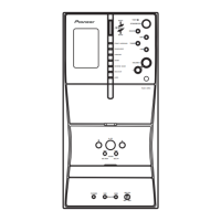
Illustration and labels for the front panel controls of the EV700/1000 model.
Explains controls for tape deck operations like REVERSE MODE, REC/STOP, ASES.
Shows the display panel and explains its character indicators.
General description of character display.
Explains the function of Karaoke ECHO and KEY indicators.
Explains indicators for B.CUT, ASES REC, REC, and tape direction/mode.
Explains indicators for Dolby Pro Logic II, Dolby Digital, and DTS.
Explains indicators for FM mono, stereo, and tuned reception.
Explains indicators for DSP sound modes like ADV.SURR. and SFC.
Explains playback indicator and speaker usage indicators.
Explains indicators for PGM, RDM, RPT-1, and REC/STOP.
Explains WAKE-UP and REC timer indicators.
Explains the DIALOGUE indicator.
Lights when line recording mode is switched on.
Switches the player on or into standby.
Selects the desired input source.
Buttons for controlling DVD playback like AUDIO and SUBTITLE.
Buttons for adjusting sound modes like X.BOOM, SFC, SURROUND.
Controls for KARAOKE and ECHO functions.
Adjusts the volume level.
Accesses on-screen menus for settings and functions.
Navigates menus and selects options.
Buttons for playback control like play, pause, stop, and slow motion.
Explains number buttons and SHIFT functions for track selection and programming.
Outputs test tone for speaker setup.
Adjusts speaker level.
Accesses functions written in green on the remote.
Mutes the volume.
Switches between information displays.
Displays the top menu of a DVD disc.
Displays the DVD menu or Disc Navigator.
Returns to the previous menu screen.
Controls the TV power, input, channel, and volume.
Lists recommended lubricants and glues for servicing.
Lists cleaning tools for pickup lenses, cassette heads, and fans.
| Channels | 5.1 |
|---|---|
| Frequency Response | 20Hz - 20kHz |
| Type | Receiver |
| Audio Formats Supported | Dolby Digital, DTS |
| Outputs | Speaker Terminals |
| Tuner | AM/FM |
| Input Sensitivity | 200mV |