6-11. LANDING GEAR FREE-FALL VALVE ASSEMBLY.
6-12. INSPECTION AND REPAIR.
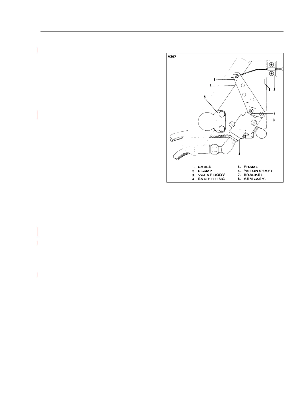
This valve is located directly above the nose
wheel actuating cylinder. Inspection is limited to
determining if any signs of hydraulic fluid leakage
are evident around the seam between the end
fitting and valve body, and around the periphery of
the piston assembly shaft. If leaks appear, the
valve assembly should be replaced since it is
impractical to repair the valve.
6-13. REMOVAL. (Refer to Figure 6-6.)
In the event it becomes necessary to replace the
free-fall valve assembly, proceed as follows:
a. Loosen three screws and clamp securing
cable in position and withdraw cable.
b. Disconnect hydraulic lines connected to the
valve. Place a rag in position to absorb any
hydraulic fluid spillage that may result. Cap
the lines to avoid contamination.
c. Remove the hex head bolts securing the valve
and bracket to the frame and remove the
assembly from the airplane.
d. Remove rivet and nut securing link to piston shaft. Note position of elbow and tee fittings to assure
their being replaced in the same position at reassembly. Remove fittings and two bolts securing the
valve to the bracket.
6-14. INSTALLATION. (Refer to Figure 6-6.)
a. Apply Loctite No. 567 PST Sealant, or equivalent, to MALE threads of elbows and tees and insert
fittings in valve. Loctite should be applied sparingly to prevent it from entering the hydraulic system.
b. Install valve on bracket and secure in position. Push piston shaft into the valve until it bottoms.
Align hole in link with hole in piston shaft and insert rivet. Attach nut to rivet.
c. Position bracket with valve on frame. Apply Loctite No. 567 PST Sealant to MALE threads of tees
and connect hydraulic lines.
d. Push arm assembly fully forward. Pull cable full forward. Place clamp over reinforced portion of
cable and tighten screws. Insert loose end of cable through the hole in the bushing of the arm
assembly. Tighten lock screw on cable.
6-15. GEAR ACTUATING CYLINDER.
6-16. REMOVAL OF NOSE GEAR ACTUATING CYLINDER.
a. Place airplane on jacks. (Refer to Jacking, Section II.)
b. Disconnect hydraulic lines from actuating cylinder and cover open line ends to prevent
contamination.
PIPER SENECA II SERVICE MANUAL
01/01/09 VI - HYDRAULIC SYSTEM
1I15
Figure 6-6. Free-Fall Valve Assembly
1.
3.
7.
8.
.