PIPER
SENECA
Il
SERVICE
MANUAL
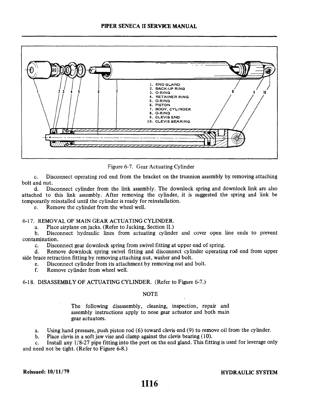
1.
ENO
GLAND
2 3 4 5
2.
BACK-UP
RING
3.
0-RING
4.
RETAINER
RING
5.
0-RING
6.
PISTON
7.
BODY,
CYLINDER
8.
0-RING
9.
CLEVIS
ENO
10.
CLEVIS
BEARING
Figure 6-7. Gear Actuating Cylinder
c.
Disconnect operating rod end from the bracket on the trunnion assembly by removing attaching
bolt and nut.
d.
Disconnect cylinder from the link assembly. The downlock spring and downlock link are also
attached
to
this link assembly. After removing the cylinder,
it
is
suggested the spring and link
be
temporarily reinstalled until the cylinder
is
ready for reinstallation.
e.
Remove the cylinder from the wheel well.
6-1
7.
REMOVAL OF
MAIN
GEAR ACTUATING CYLINDER.
a.
Place airplane on jacks. (Refer to Jacking, Section II.)
b.
Disconnect hydraulic lines from actuating cylinder and cover open line ends
to
prevent
contamination.
c.
Disconnect gear downlock spring from swivel fitting at upper end
of
spring.
d. Remove downlock spring
swivel
fitting and disconnect cylinder operating rod end from upper
side brace retraction fitting by removing attaching nut, washer and bolt.
e.
Disconnect cylinder from its attachment
by
removing
nut
and bolt.
f.
Remove cylinder from wheel
well.
6-18. DISASSEMBLY OF ACTUATING CYLINDER. (Refer to Figure 6-7.)
NOTE
The following disassembly, cleaning, inspection, repair and
assembly instructions apply
to
nose gear actuator and both main
gear actuators.
a.
Using hand pressure, push piston rod (6) toward clevis end (9) to remove oil from the cylinder.
b.
Place
clevis
in a soft jaw
vise
and clamp against the
clevis
bearing (10).
c.
Install any 1/8-27 pipe fitting into the port on the end gland. This fitting
is
used for leverage only
and need not
be
tight. (Refer to Figure 6-8.)
Reissued: 10/11/79
HYDRAULIC
SYSTEM
1116