PIPER SENECA II SERVICE MANUAL
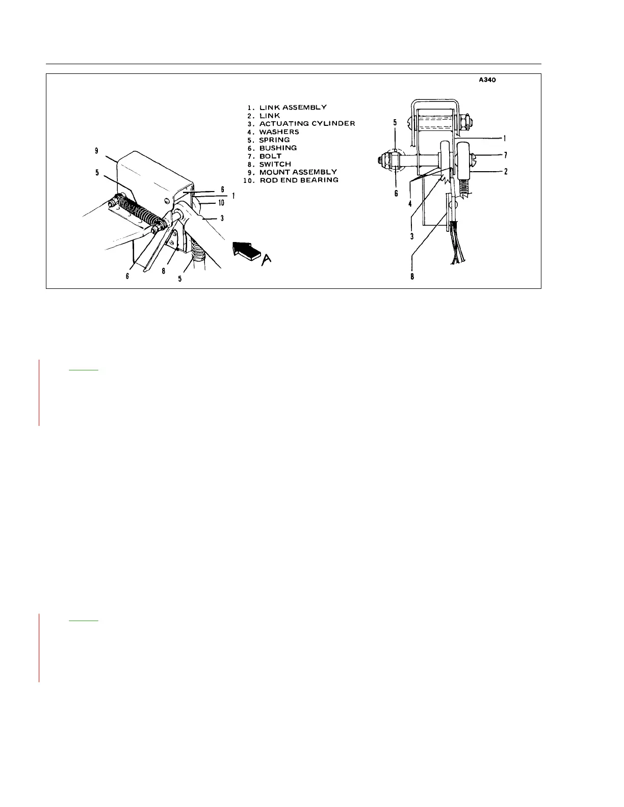
Figure 6-9. Nose Gear Actuating Cylinder Installation
6-21. INSTALLATION OF NOSE GEAR ACTUATING CYLINDER. (Refer to Figure 6-9.)
NO
TE: The following instructions apply to actuators P/N 96860-000 (i.e. - SFA232-3 and SFA232-4)
only. Disassembly, Assembly, and Cleaning, Inspection and Repair instructions for later model
actuators P/N 96860-002 and 96860-003 (i.e. - SFA232-5) are found in Cleveland Wheel and
Brakes publication: Component Maintenance Manual - CMSFA232-5 (011-00504) available
from the vendor. See Vendor Publications in the Introduction.
a. Refer to Paragraph 6-16, step d. Remove bolt (7) far enough to position clevis end of actuating
cylinder (3) in the link assembly (1). Reinsert bolt with callouts (1) thru (6) arranged as illustrated in
Figure 6-9.
b. Insert the operating rod end into the bracket on the trunnion assembly and secure with bolt, nut and
washers.
c. Connect hydraulic lines to their respective fittings on the actuating cylinder.
d. Check adjustment of cylinder rod end. (Refer to Adjustment of Nose Landing Gear, Section VII.)
e. Operate pump to purge system of air and check fluid level in reservoir.
f. Remove airplane from jacks.
6-22. INSTALLATION OF MAIN GEAR ACTUATING CYLINDER.
NO
TE: The following instructions apply to actuators P/N 96860-000 (i.e. - SFA232-3 and SFA232-4)
only. Disassembly, Assembly, and Cleaning, Inspection and Repair instructions for later model
actuators P/N 96860-002 and 96860-003 (i.e. - SFA232-5) are found in Cleveland Wheel and
Brakes publication: Component Maintenance Manual - CMSFA232-5 (011-00504) available
from the vendor. See Vendor Publications in the Introduction.
a. Attach the cylinder to its attachment fitting in the wheel well using bolt and nut.
b. Attach the operating rod end and downlock spring swivel fitting to the upper side brace retraction
fitting using washer and nut. The swivel fitting must be free to rotate.
VI - HYDRAULIC SYSTEM 01/01/09
1I20
l.
2.
3.
4.
5.
6.
7.
8.
9.
10.