PIPER SENECA
II
SERVICE MANUAL
D.
C.
BUS
'----------t
V
CAUTION:
SUGGESTED
METER
SIMPSON
#260
OR
EQUV.
RANGE
0-50V
B
0-5V
DC
FIELD
V/M
CIRCUIT MUST NOT
TOUCH
GROUND.
NOTE:
THIS DIAGRAM
SHOWS
ONLY BASIC
CONNECTIONS
FOR
THE
PURPOSE
OF
EXPLAINING ADJUSTMENT PROCEDURE.
BUS
GND
REGULATOR
"Bu
FIELD
PAR
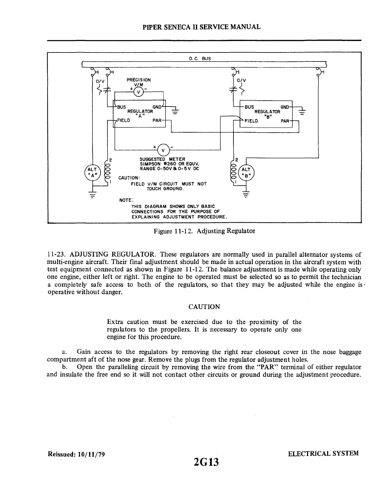
Figure 11-12. Adjusting Regulator
11-23. ADJUSTING REGULATOR. These regulators are normally used in parallel alternator systems
of
multi-engine aircraft. Their final adjustment should be made in actual operation in the aircraft system with
test equipment connected as shown in Figure 11-12. The balance adjustment is made while operating only
one engine, either left or right. The engine to be operated must be selected
so
as
to permit the technician
a completely safe access to
both
of
the regulators, so
that
they may
be
adjusted while the engine is·
operative without danger.
CAUTION
Extra caution must be exercised due to the proximity of the
regulators to the propellers. It
is
necessary
to
operate only one
engine for this procedure.
a.
Gain access to the regulators by removing the right rear closeout cover in the nose baggage
compartment aft
of
the nose gear. Remove the plugs from the regulator adjustment holes.
b. Open the paralleling circuit by removing the wire from the "PAR" terminal
of
either regulator
and insulate the free end
so
it will not contact other circuits or ground during the adjustment procedure.
Reissued: 10/11/79
2G13
ELECTRICAL
SYSTEM