R-C
FILTER
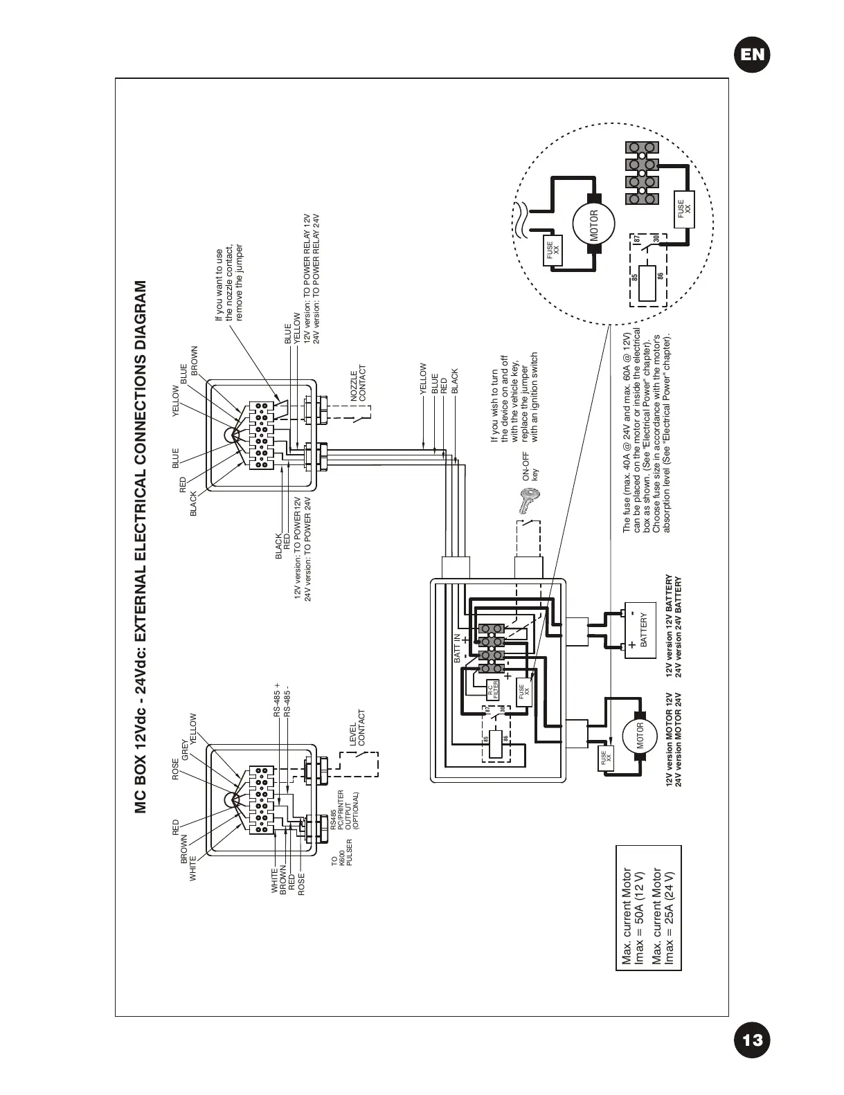
If you want to use
the nozzle contact,
remove the jumper
If you wish to turn
the device on and off
with the vehicle key,
replace the jumper
with an ignition switch
The fuse (max. 40A @ 24V and max. 60A @ 12V)
can be placed on the motor or inside the electrical
box as shown. (See "Electrical Power" chapter).
Choose fuse size in accordance with the motor's
absorption level (See "Electrical Power" chapter).
24V version: TO POWER 24V
12V version: TO POWER RELAY 12V
24V version: TO POWER RELAY 24V
WHITE
RED
BROWN
ROSE
GREY
YELLOW
BROWN
WHITE
RED
ROSE
RS-485 +
RS-485 -
TO
K600
PULSER
RS485
PC/PRINTER
OUTPUT
(OPTIONAL)
LEVEL
CONTACT
ON-OFF
key
FUSE
XX
FUSE
XX
85
86
87
30
FUSE
XX
MOTOR
FUSE
XX
Max. current Motor
Imax = 50A (12 V)
Max. current Motor
Imax = 25A (24 V)
EN