16
ICOMMISSIONING
To correctly commission the MC BOX the sequence of operations indicated below
must be followed and the MC control system functions must be known (see attached
manual).
Once the power connections have been made, the MC BOX can be energised by
means of the master switch to be fitted by the installer on the upstream line.
Switching on of the MC system will be indicated by the lighting up of the two backlit
LCDs fitted on the front.
NOTE:
In the event of continuous current power supply (DC), a fuse size that is appropriate
to the DC motor's absorption level should be introduced to the motor
power line.
For example:
•If the connected motor is one that absorbs 10A max then a 12A delay fuse should be
inserted.
• If, however, the motor absorbs 50A max, then a 60A delay fuse should be inserted.
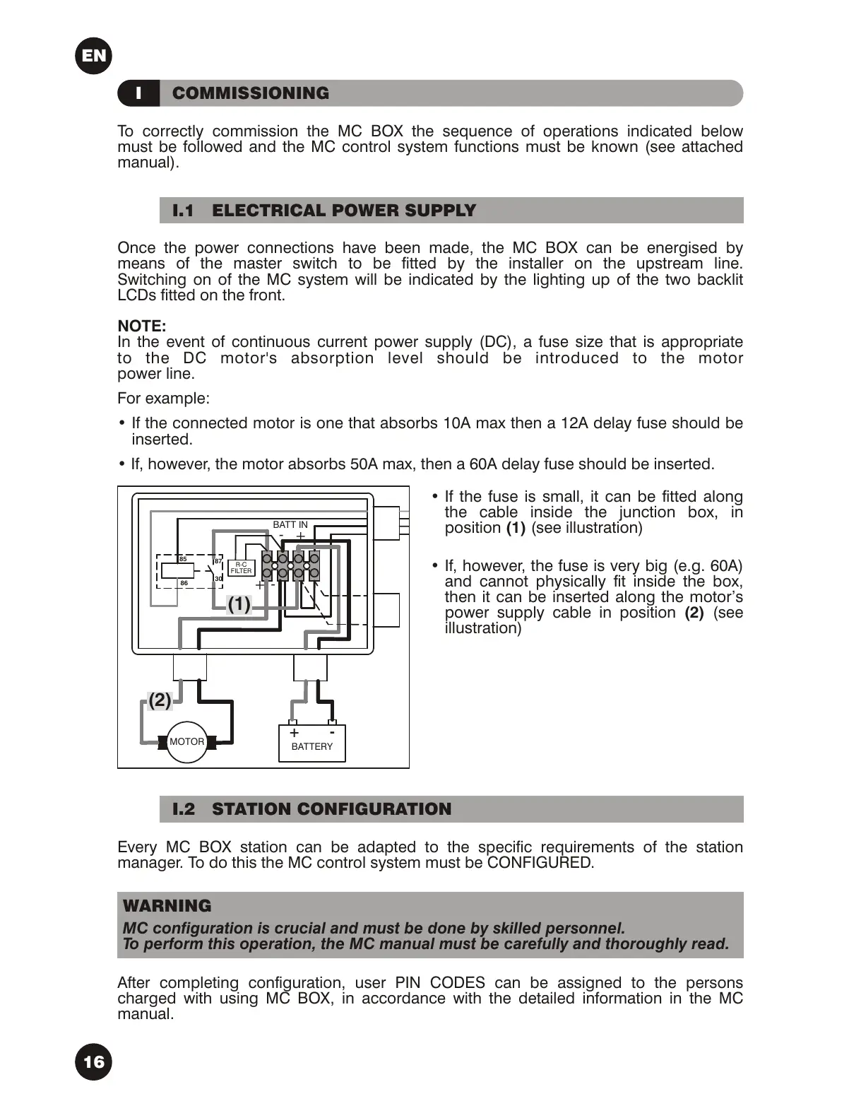
•If the fuse is small, it can be fitted along
the cable inside the junction box, in
position (1) (see illustration)
•If, however, the fuse is very big (e.g. 60A)
and cannot physically fit inside the box,
then it can be inserted along the motor’s
power supply cable in position (2) (see
illustration)
I.1ELECTRICAL POWER SUPPLY
Every MC BOX station can be adapted to the specific requirements of the station
manager. To do this the MC control system must be CONFIGURED.
After completing configuration, user PIN CODES can be assigned to the persons
charged with using MC BOX, in accordance with the detailed information in the MC
manual.
I.2STATION CONFIGURATION
MC configuration is crucial and must be done by skilled personnel.
To perform this operation, the MC manual must be carefully and thoroughly read.
WARNING
EN