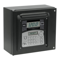
15
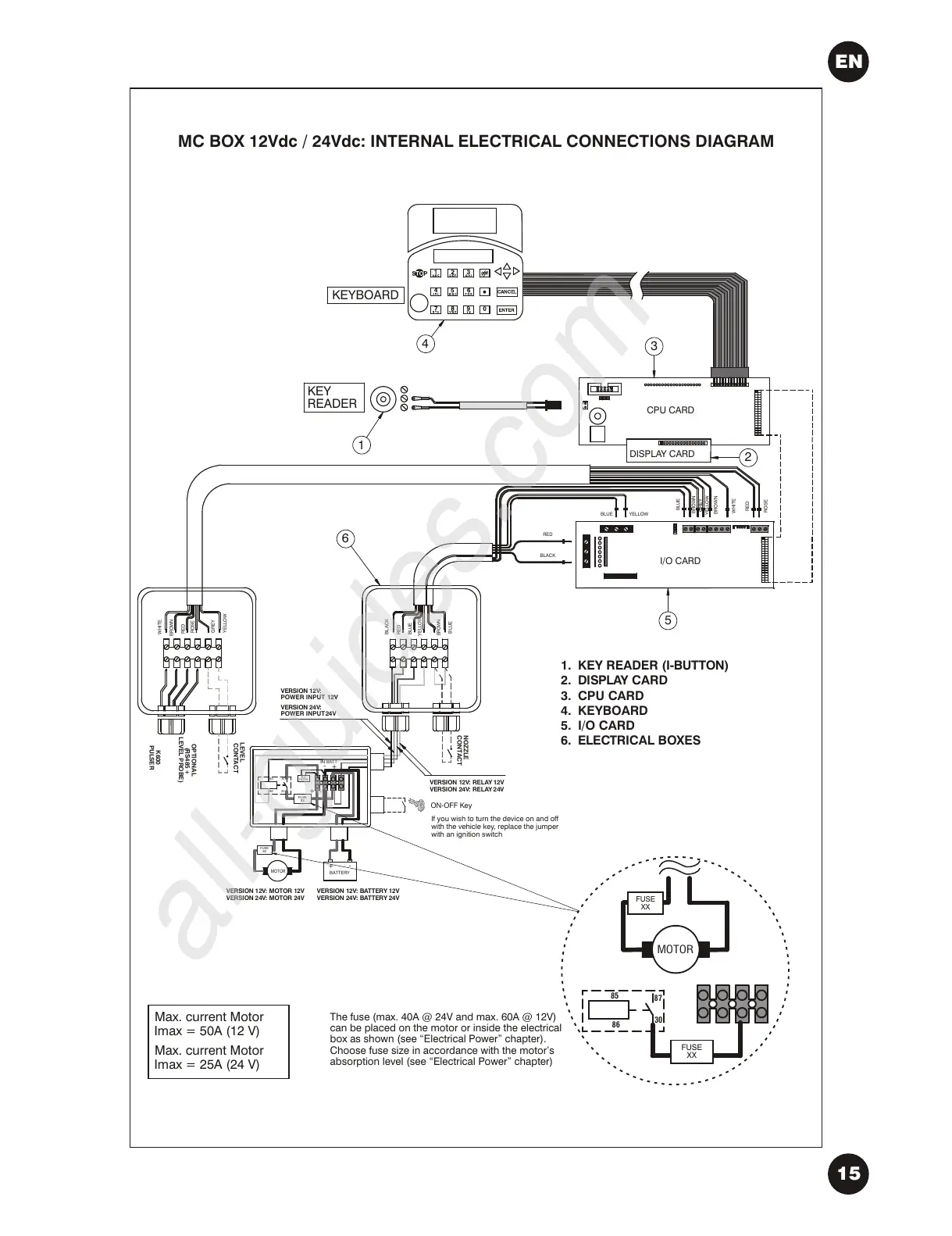
CPU CARD
DISPLAY CARD
KEY
READER
KEYBOARD
I/O CARD
VERSION 12V:
POWER INPUT 12V
WHITE
VERSION 12V: MOTOR 12V
VERSION 24V: MOTOR 24V
85
86
87
30
+
-
IN BATT
-
+
BATTERY
MOTOR
+
-
OPTIONAL
(RS485 +
LEVEL PROBE)
K600
PULSER
LEVEL
CONTACT
BROWN
RED
ROSE
GREY
YELLOW
NOZZLE
CONTACT
BLACK
RED
BLUE
YELLOW
BROWN
BLUE
1
2
3
4
5
6
1.
2.
3.
4.
5.
6.
KEY READER (I-BUTTON)
DISPLAY CARD
CPU CARD
KEYBOARD
I/O CARD
ELECTRICAL BOXES
YELLOW
BLUE
BROWN
GREY
YELLOW
BROWN
WHITE
RED
ROSE
RED
BLACK
FILTER
R-C
VERSION 24V:
POWER INPUT 24V
VERSION 12V: BATTERY 12V
VERSION 24V: BATTERY 24V
VERSION 12V: RELAY 12V
VERSION 24V: RELAY 24V
BLUE
MC BOX 12Vdc / 24Vdc: INTERNAL ELECTRICAL CONNECTIONS DIAGRAM
The fuse (max. 40A @ 24V and max. 60A @ 12V)
can be placed on the motor or inside the electrical
box as shown
Choose fuse size in accordance with the motor’s
absorption level (see “Electrical Power” chapter)
(see “Electrical Power” chapter).
If you wish to turn the device on and off
with the vehicle key, replace the jumper
with an ignition switch
ON-OFF Key
FUSE
XX
FUSE
XX
85
86
87
30
FUSE
XX
MOTOR
FUSE
XX
Max. current Motor
Imax = 50A (12 V)
Max. current Motor
Imax = 25A (24 V)
EN