4
Wiring
Chart
Wiring
Chart
ア
イ
ヴィッツ
車名
H17.
メーカー
TOYOTA
クラッチ関 係
MTC-7
クラッチ
スイッチ
コネクター
形状
クラッチ
アダプター
○: 使 用 す る
×: 使 用 し な い
クラッチアダプター
のコード色
ユニットの
コード色
接続記号
ア
茶紫
ピンク
○
ア
イ
Features
Connecting
The Wires
Installing
The Product
How to
Operate
Speed Pulse
Settings
Before
Using
Trouble-
Shooting
Initial
Settings
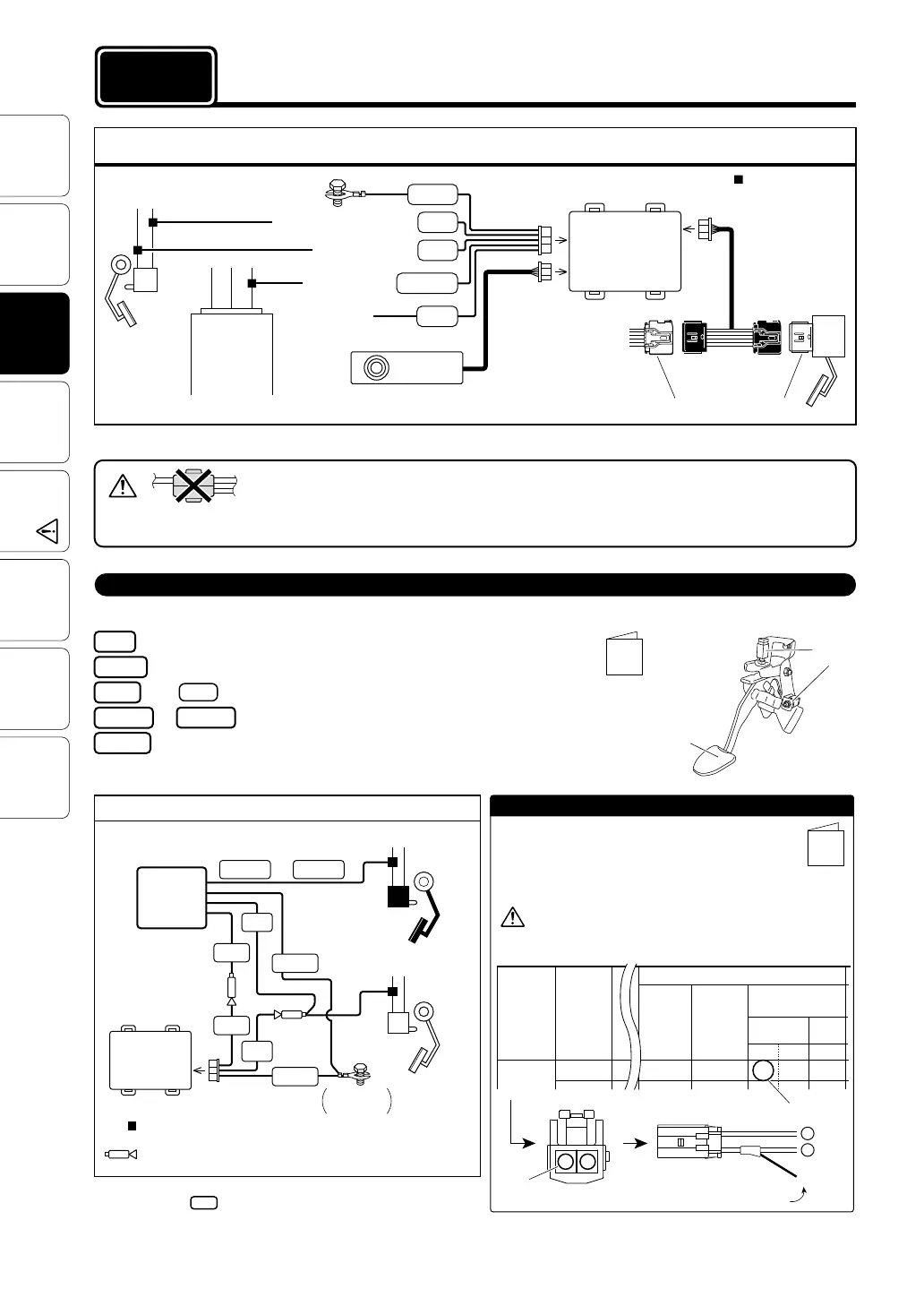
Note: For some car models like 86/BRZ with push button start system,
connect directly code from 8-pin Connector of the unit side to
Clutch Switch Signal without using Clutch Adapter.
To Brake Power (normal 12V)
Clutch Signal (Use included Clutch Adapter)
Red
To Earth
To Pink code of 8-pin Connector
Black
Pink
To Clutch Signal
Brown Purple
Spare wiring (usually not used)
Green
or
Connecting the Clutch Adapter
• Connect the wires of Clutch switch
signal to the corresponding wires
found in the “Wiring Chart”.
• The car which has 2 clutch switch connec-
tors, choose one which works with depress-
ing the clutch pedal.
• Cut off the insulation of the tip of the codes,
among of Brown and Purple and Green
code which you need to connect, then
bundle the extra code.
e.g. TOYOTA Vitz (from Feb. 2005)
Wire leading
from Clutch Adapter
Connection
letter
Unit
Clutch
Clutch
Adapter
Clutch
Switch
Brake
Brake
Switch
or
Pink
Pink
Red
Red
Black
Brown Purple
Black
Earth
8-pin Connector
(Brake Power)
Basic Wiring
(Clutch Switch Signal)
Brown
Switch Connector
How to Connect
1.
Check the wiring of Clutch Switch Signal ,necessity of
Clutch Adapter and the corresponding wire colors in
the included "Wiring Chart".
2. Connect the wires using included Cut connectors.
Note that the colors listed in the chart under “Clutch
Adapter Wire Color” are not the colors of the wires on
the car side.
Brown
: Use Cut Connector
(Refer to page 6 [Reference 2] “How to use the Cut Connectors” )
: Use Male Connector
(Refer to page 6 [Reference 3] “How to use the Male Connectors” )
Fastened two
terminals
Connecting The Wires
procedure 1
Basic Wiring
When installing make sure to use the correct Specialized Harness for your car model.
Note 1: After inserting the connector, pull lightly to make sure that it is securely locked.
• When connecting to the car side wires, do not only use “electrotap” as this may result in a poor
electrical connection. Please use the supplied “cut connectors” or solder the wires together and
make sure to use insulation tape to securely insulate the wire connection.
• The Brake Switch Connectors will differ depending upon the car model, grade and year, so please sure to check the design in the “Wiring Chart”.
• Remove the battery cables from the minus terminals before carrying out the wiring.
: Use Cut Connector
Unit
Accelerator Connector
Special Model
Specific Harness
(sold separately)
Accelerator
6-pin Connector
5-pin
Connector
8-pin Connector
Brake
SP
Option
Connector
ECU, etc...
Brake
Switch
Clutch Signal
(⇒See the bottom of this page)
Controller
Earth
Gray
Red
Black
Pink
Orange
Brake Power (normal 12V)
Brake Switch Signal
Car Speed Signal
Clutch
Pedal
Clutch
Switch
(MTC-7)
Pink
(Refer to page 6 [Reference 2] “How to use the Cut Connectors” )
(1.5m)
(1.5m)
(1.5m)
(1.5m)
(1.5m)
(0.5m)
(1.5m)
(See Note 1)
(See Note 1)
(See Note 1)