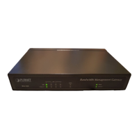
BM-500 Bandwidth Management Gateway User’s Manual
- 7 -
Chapter 3: Getting Started
3.1 Web Configuration
STEP 1:
Connect both the Administrator’s PC and the LAN port of the Bandwidth Management Gateway to a hub or
switch. Make sure there is a link light on the hub/switch for both connections. The Bandwidth Management
Gateway has an embedded web server used for management and configuration. Use a web browser to
display the configurations of the Bandwidth Management Gateway (such as Internet Explorer 4(or above) or
Netscape 4.0(or above) with full java script support). The default IP address of the Bandwidth Management
Gateway is 192.168.1.1 with a subnet mask of 255.255.255.0. Therefore, the IP address of the Administrator
PC must be in the range between 192.168.1.2– 192.168.1.254
If the company’s LAN IP Address is not subnet of 192.168.1.0, (i.e. LAN IP Address is 172.16.0.1), then the
Administrator must change his/her PC IP address to be within the same range of the LAN subnet (i.e.
172.16.0.2). Reboot the PC if necessary.
By default, the Bandwidth Management Gateway is shipped with its DHCP Server function enabled. This
means the client computers on the LAN network including the Administrator PC can set their TCP/IP settings
to automatically obtain an IP address from the Bandwidth Management Gateway.
The following table is a list of private IP addresses. These addresses may not be used as a WAN IP address.
10.0.0.0 ~ 10.255.255.255
172.16.0.0 ~ 172.31.255.255
192.168.0.0 ~ 192.168.255.255
STEP 2:
Once the Administrator PC has an IP address on the same network as the Bandwidth Management Gateway,
open up an Internet web browser and type in http://192.168.1.1 in the address bar.
A pop-up screen will appear and prompt for a username and password. A username and password is required
to connect to the Bandwidth Management Gateway. Enter the default login username and password of
Administrator (see below).
Username: admin
Password: admin
Click OK.