14
2.3 Rear Panel
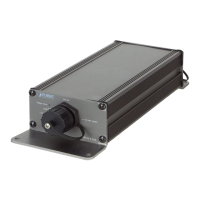
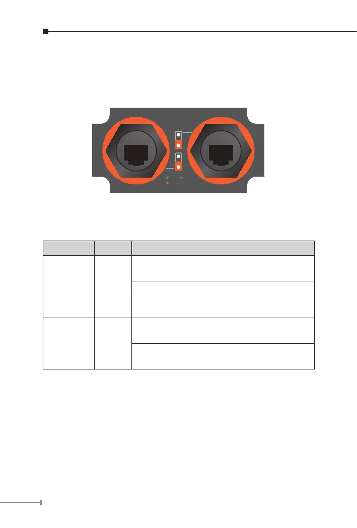
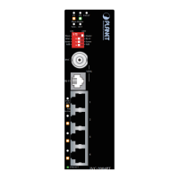
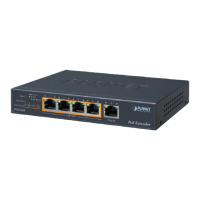
Figure 2-2 shows the rear panel of the industrial Power over Ethernet
extender
ACTLNK
PoE In-use
PoE 1 Out PoE 2 Out
Figure 2-2: IPOE-E202 Rear Panel
PoE Output Port (Port 1 ~ 2)
LED Color Function
LNK/ACT Green
Lights to indicate the port is linked up at
10/100/1000Mbps.
Blinks to indicate that the IPOE-E202 is
actively sending or receiving data over that
port.
PoE-in-Use Orange
Lights to indicate the port is providing PoE
power.
Off to indicate the connected device is not a
PoE Powered Device (PD).
2.4 Mounting Installation
This section describes how to install the industrial PoE extender and
make connections to it. Please read the following topics and perform
the procedures in the order being presented.