MB502 6” Deluxe Jointer
16
Use only 3-wire extension cords that have grounding type plugs and receptacles that
accept the tool’s plug.
Repair or replace damaged or worn cord immediately.
CAUTION: IN ALL CASES, MAKE CERTAIN THE RECEPTACLE IN QUESTION IS
PROPERLY GROUNDED. IF YOU ARE NOT SURE HAVING A CERTIFIED
ELECTRICIAN CHECK THE RECEPTACLE.
OPERATING CONTROLS AND ADJUSTMENTS
STARTING AND STOPPING JOINTER
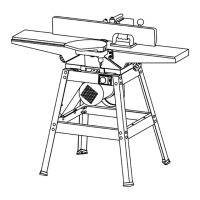
The safety magnetic switch (A) Fig. 19, is located on the topside brace of the stand. To
turn the machine “ON”, push button “I” on switch (A). To turn the machine “OFF”, push the
button “O” on the switch (A). The magnetic switch is a no volt switch, if power source is cut
off accidentally, you have to push the button “I” to restart the unit again.
Fig. 19
OUTFEED TABLE ADJUSTMENTS
For most jointing operations the outfeed table must be exactly level with the knives at their
highest point of revolution. This means that the knives must be parallel to the outfeed table
and project equally from the cutterhead. To move the outfeed table up of down, loosen
lock screw Fig. 20, and turn hand knob (B). When the outfeed table is exactly level with
the knives at their highest point of revolution, tighten lock screw (A).