MB502 6” Deluxe Jointer
9
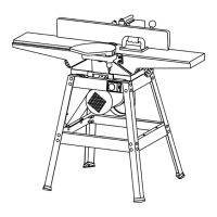
ASSEMBLING MOTOR AND SWITCH BOX TO STAND
1. The motor (B) Fig.8 is assembled to the bottom of the dust chute using the four 1-1/4”
long carriage bolts (A) (not shown on the drawing), flat washers, lock washers and hex
nuts. Do not completely tighten hex nuts at this time, as the motor must be adjusted
for proper alignment and belt tension later.
2. Assemble the switch box (C) Fig. 8, to the inside of switch opening (B) (refer to Fig. 7)
using the two 3/8” long screws, and flat washers.
Fig. 8
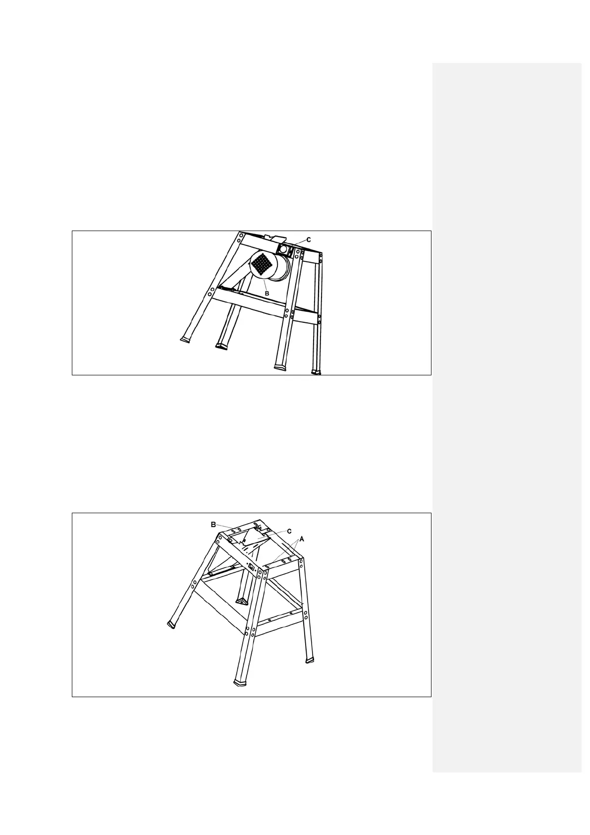
ASSEMBLING JOINTER TO STAND
1. WARNING: JOINTER WEIGHTIS APPROXIMATELY 75KGS. CARE MUST BE
TAKEN WHEN LIFTING JOINTER ONTO STAND. A MINIMUM OF TWO PEOPLE
WILL BE REQUIRED TO LIFT THE MACHINE.
2. The infeed end of the jointer is fastened to the two holes (A) Fig. 9, and the outfeed
end of the jointer is fastened to hole (B) on the two top end braces. NOTE: Dust chute
(C) is on outfeed end of jointer. Line up the three threaded holes on the bottom of the
jointer with the three holes (A) and (B) in the stand end braces.
Fig. 9