13
Chapter 2. Hardware Description
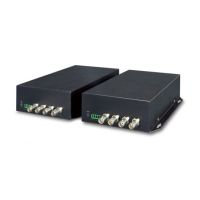
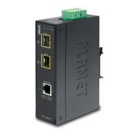
2.1 Front Panel
The front panel of the VF-101G-T/VF-101G-R comes with
two ber optic interfaces and one video socket, while those
of the VF-102G-T/VF-102G-R and VF-106G-T/VF-106G-R
each have one ber optic interface and one video socket.
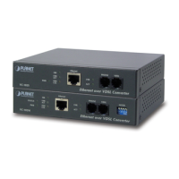
For the VF-101G/102G/106G-T and VF-101G/102G/106G-R,
With the reverse data connector, the RS485 data port of the
VF-101G/102G/106G-T or VF-101G/102G/106G-R can be
connected to the user’s interface.
PWR
GND
LNK
Video
over
Gigabit
Fiber
Converter
OPTIC
VIDEO
RS485
PWR
GND
LNK
Video
over
Gigabit
Fiber
Converter
OPTIC
VIDEO
RS485
VF-101G-T/VF-101G-R VF-102G-T/VF-102G-R
PWR
GND
LNK
Video
over
Gigabit
Fiber
Converter
OPTIC
VIDEO
RS485
VF-106G-T/VF-106G-R
z Video Interface
Video
Connection
Connect the video signal to or from the product
through a 75Ω coax cable with BNC plug.
Async-data
Connection
zConnect the output data port (e.g. TX+ and
TX-) of the other controlled device to the RX+
and RX- of the RX.
zConnect the input data port (e.g. RX+ and RX-)
of the other controlled device to the TX+ and
TX- of the TX.
zGND in both TX and RX should be connected
directly to user’s equipment.
Fiber
Connection
Connect the ber-optic cable pigtail to the
product’s ber port.