16
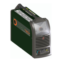
VOLTAGE DIVIDER SETTINGS
The secondary voltage divider is set in the factory at a value
of 1:50.
Inside the machine there is a dip-switch (SW1) that can be used
to set 4 other secondary voltage values:
1:20 1:21 1:30 1:40
To access the dip-switch (SW1) proceed as follows (Fig. O):
1) Disconnect the power supply from the system by turning
the line switch on the back panel to the O position. Discon-
nect the machine’s power supply cable from the main pow-
er supply socket in the wall.
2) Remove the machine’s metal bottom plate to access the
machine’s secondary board.
3) Set the dip-switch (SW1) to one of the configurations avail-
able.
4) Reassemble the machine, following the points above in re-
verse order.
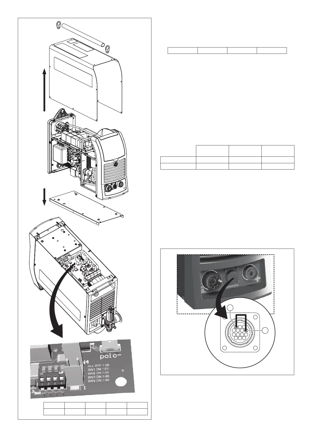
USING THE MANUAL PLASMA TORCH ON PLASMA
SHARK, “M” VERSION PLANTS
Manual torches can be used on SHARK “M” version plasma
plants for automatic plants as well:
Automatic
cutting torch
Manual torch Length
SHARK 75/M SKM 75 SK 75 6-12 m
SHARK 105/M SKM 125 SK 125 6-12 m
The manual torches can work in SHARK “M” version plants only
if terminals 3 and 4 are short-circuited on the 14 pole male con-
nector used to interface with the CNC controller plants (Fig. P).
Code 460180: buying code for the 14 pole male connector used
to interface with CNC controller plants.
4
3
FIG. P
FIG. O
ALL OFF SW1 ON SW2 ON SW3 ON SW4 ON
1:20 1:21 1:30 1:40 1:50