15
FIG. N
13
12
4
14
6
3 5
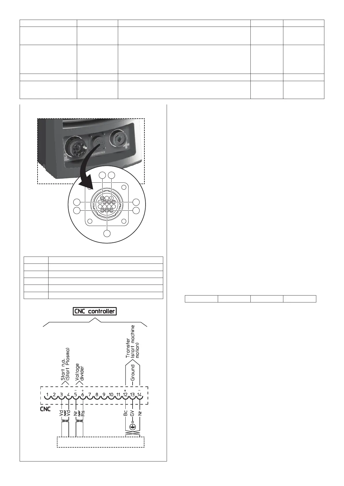
Signal Type Notes Pole n° Wire colour
Start cut Input An isolated contact has to be closed for activation to
occur. The characteristics of this contact are: voltage >
20 Vdc; current > 10 mA.
3
4
Green
Green
Arc transferred
Start machine
movement
Output Closure of isolated photo relay contact. This contact’s
characteristics are as follows:
• Max voltage 60 Vdc
• Max current 400 mAdc
Alternating current (AC) is not allowed.
12 (+)
14 (-)
White (+)
Black (-)
Earth protection (PE) Earth 13 Yellow Green
Reduced cutting
voltage
Output Signal proportional to the cutting voltage, not
galvanically isolated, according to the following ratios:
1:50 (factory setting); 1:20; 1:21; 1:30; 1:40.
5 (-)
6 (+)
Black (-)
Red (+)
SHARK 75/M - SHARK 105/M
CNC Female 14 pole connector
Vd Green wire
Nr Black wire
Rs Red wire
Bc White wire
GV Yellow / green wire
If the cutting bench’s guides and transmission system are
cleaned, checked and optimised, the torch moves easily. Un-
steady movement of the machine can give rise to an undulat-
ing, irregular path on the cutting surface.
Make sure that the torch does not touch the plate while cut-
ting. Contact could damage the shield and nozzle, and affect
the cut surface.
Having connected to the torch to the X-Y-Z bench, screw it to
the centralised connection on the SHARK system generator.
The two-pole cable that sticks out about 2 m from the central-
ised connection for the SKM plasma torch, is in series with the
start cut button.
Depending on the type of X-Y-Z bench and the software used,
the two-pole cable can be used as:
•
An additional emergency stopping unit for the mechanised
cutting machine.
•
A short-circuit for the 2 wires of the two-pole cable, if used as
an emergency stopping unit.
INTERFACE WITH A CNC CONTROLLER PLANT
The special SHARK 75/M and SHARK 105/M plasma versions,
are already complete with an interface for CNC controller equip-
ments, such as X-Y-Z cutting benches, for example.
On the front of the SHARK 75/M and SHARK 105/M machine
there is a 14-pole female connector (CPC TE Connectivity se-
ries) for connecting the CNC interface cable.
This socket makes the following signals available:
•
Arc voltage reduced to 1:50 (factory setting), with a maximum
output of 15 V (NOT galvanically isolated signal). Inside the
SHARK machine there is a dip-switch that can be used to
set other reduced arc voltages:
1:20 1:21 1:30 1:40
• Arc transfer / start machine movement signal
• Start cut signal.
The machine interface cable must be installed by a technician
from an authorised service centre.
To install the machine’s interface cable:
• Disconnect the power supply to the machine, by shifting the
switch to the O position.
•
Connect the machine’s interface cable to the 14-pole CNC
controller socket located on the front panel of the SHARK
75/M and SHARK 105/M machines. The male 14-pole in-
terface connector (CPC TE Connectivity series) is available
from our Company, using order code 460180.
FEMALE 14-POLE MACHINE INTERFACE
CONNECTOR OUTPUTS
On the front of the SHARK 75/M and SHARK 105/M machine
there is a 14-pole female connector (CPC TE Connectivity se-
ries) for connecting a CNC controller cable or a height con-
troller.
The signals available on the machine interface connector, are
indicated in figure N.