13
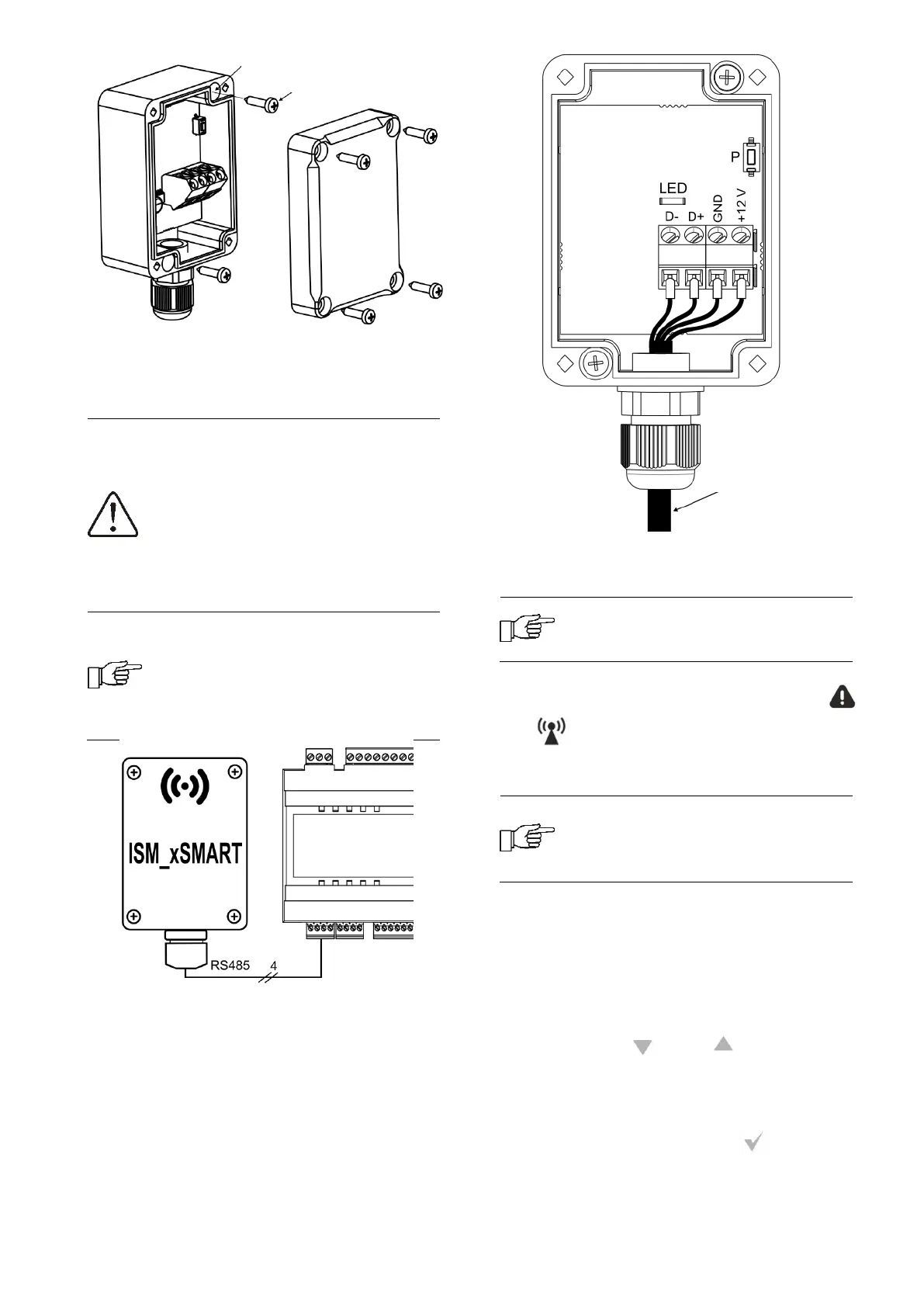
Terminals D +, D-, GND, 12 VDC of the radio
module should be connected to the RS485
transmission socket of the main controller, in
accordance with point. 15.5
When connecting the transmission
and power supply attention should
be paid to the proper polarity of
connection of D +, D- and GND, 12
V between the radio module and the
main controller. Improper
connection may lead to damage to
the main controller or errors in its
operation.
The maximum cable length depends
on the cross-section of the wires.
For a 0.5 mm
2
wire, it should not
exceed 30 m. The cross-section
should not, however, be less than
0.5 mm
2
.
15.2 Pairing the radio module with the
thermostat
The radio module connected
electrically to the main controller
requires pairing with a thermostat.
Until the pairing with the radio module on
the thermostat screen is complete, the
and symbols are permanently displayed.
Pairing from the main controller menu:
The pairing method is only available
when the main controller program is
fully compatible with the radio
module.
Enter the main regulator menu:
MENU → General settings → Radio
module settings → Pairing mode and set
the Pairing mode to Yes, then the pairing
mode will be activated for 4 minutes, during
this time the thermostat with the radio
module should be paired. To do this, hold
simultaneously and button for 2
seconds in the thermostat and then select
the program (P03) in the user menu of the
thermostat, where "PAr" is displayed on the
screen. After accepting with button, the
pairing will start (the word "PAr" begins to
flash).
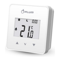
Screw holes
Assembly screw
4x0.5 mm
2
wire,
max. length 30 m
Assembly screw