LC1000 INSTRUCTION MANUAL INSTALLATION DETAILS
PAGE 14
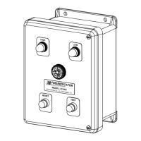
2.2 CONTROL CONSOLE INSTALLATION
The console is the center of operations for any tank monitor system therefore its location should be
selected for the operator’s convenience, or as specified on the DESIGN DRAWINGS.
Select a flat wall surface and prepare it with four wall-mounting inserts to accept up to 1/4-inch size
bolts. Allow sufficient room for door to open and for conduit runs to enter ONLY THE CONSOLE
BOTTOM. See Figures 1-2 or 1-3 for the appropriate console dimensions.
Note that the console is divided into two electrical areas:
INTRINSICALLY SAFE (LEFT SIDE) NON INTRINSICALLY SAFE (RIGHT SIDE)
for Sensor signals and IS Earth Grounds for Power and Control
Figures 2-1 and 2-2 show the console interior, again indicating the power and signal separation. THIS
SEPARATION MUST BE MAINTAINED when conduits are connected. Refer to Section 3 for
electrical conduit and wiring.
Figure 2-1 – LC1001/1002 Control Console Interior
(LC1002 shown)
DRAWING NO. 20110 REV. N/C
I.S. COMPARTMENT COVER
(SHOWN OUTSIDE CONSOLE)
FUSE
FUSE COVER
I.S. COMPARTMENT COVER
(SHOWN INSTALLED)
MOUNTING PLATE
I.S. GROUNDS
I.S. INPUTS1 & 2 FOR LC1002.
I.S. INPUT 1 (INPUT 2 NOT ACTIVE)
FOR LC1001
NON I.S. OUTPUTS 1 & 2 FOR LC1002.
NON I.S. OUTPUT 1 (OUTPUT 2 NOT ACTIVE)
FOR LC1001
POWER
CONDUIT
GROUNDING PLATE
 Loading...