31
The above are the judgment and inspection of common failures.
Please do not disassemble the unit by yourself to avoid any dangers and
damages to the induction hob.
GB
Heating zones of
the same side
( Such as the first
and the second
zone ) would
display “ ” .
The power board and
the display board
connected failure;
Check the connection.
Fan motor sounds
abnormal.
The fan motor is
damaged.
Replace the fan.
The display board of
communicate part is
damaged.
Replace the display board.
The Main board is
damaged.
Replace the power board.
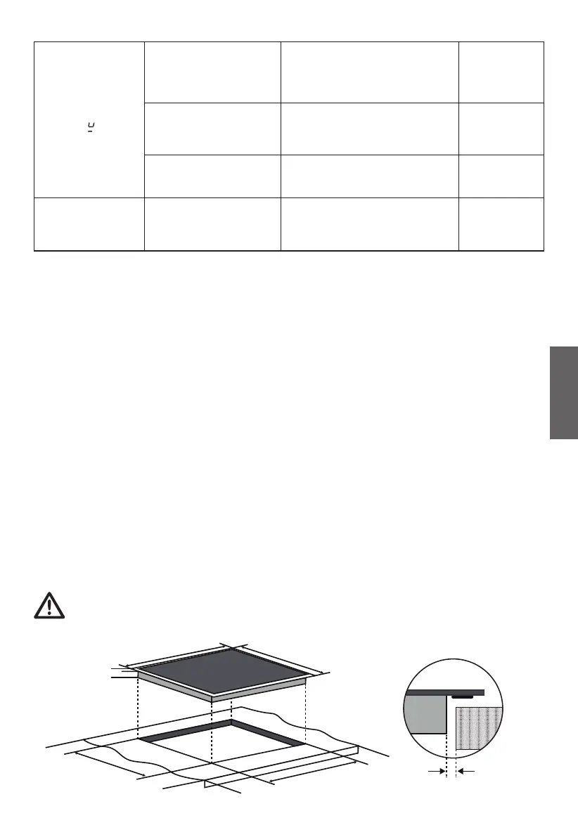
Note: The safety distance between the sides of the hob and the
inner surfaces of the worktop should be at least 3mm.
SELECTION OF INSTALLATION EQUIPMENT
INSTALLATION
Cut out the work surface according to the sizes shown in the drawing.
For the purpose of installation and use, a minimum of 5 cm space shall be
preserved around the hole.
Be sure the thickness of the work surface is at least 30mm. Please select
heat-resistant and insulated work surface material (Wood and similar
fibrous or hygroscopic material shall not be used as work surface material
unless impregnated) to avoid the electrical shock and larger deformation
caused by the heat radiation from the hotplate. As shown below:
3mm Min.
F
H
D
L
W
x
x
x
B
A
SEAL