TONEOHM 950 OPERATOR MANUAL
4-2
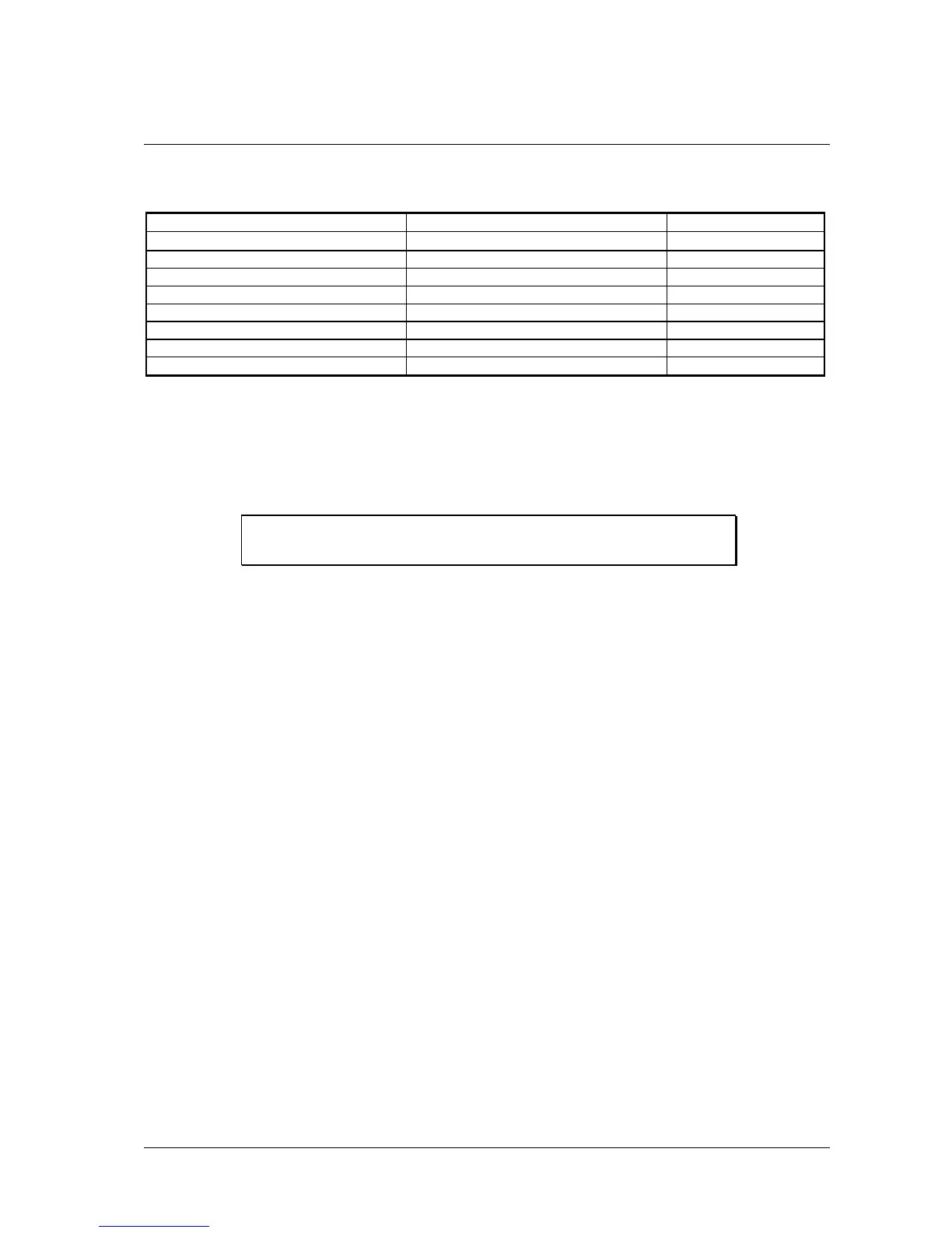
Table 4-1 indicates the suggested range for locating different types of short circuit.
Type of fault Range Section
Shorts below 200 mΩ [Ω], 200 mΩ
4.2
Multi-layer shorts (static) PLANE SHORTS 4.3
Multi-layer shorts (dynamic) 200mA 4.4
Excessive Vcc loads 200mA 4.4
Stuck Bus line (static) TRACE, 200mA 4.5, 4.4
Stuck Bus line (dynamic) 200mA 4.4
Backplanes/wiring harnesses TRACE 4.5
Open Circuit Capacitor TRACE 4.5
Table 4-1 Range selection
4.2 (Low resistance) shorts
NOTE: Disconnect power from the board under test before using any of
the resistance ranges.
Low resistance shorts are shorts having a resistance under 200 mΩ, caused typically by a solder or land
bridge. They often occur between adjacent tracks or solder joints on a PCB. Resistance measurements,
using the 200 mΩ range, should isolate the fault to within a few millimetres.
In situations where tracks are thick, more sensitivity and resolution can be gained using the [Ω] range.
As the 950 uses DC for resistance measurement, capacitors do not affect its accuracy. The open circuit
probe tip voltage is limited to a maximum of 60mV to prevent any damage to sensitive components.
To obtain the best results and minimise damage to the track, hold the probes at right angles to the PCB
and apply sufficient pressure to pierce flux and solder resist. Probe the track at different points rather than
scraping the probe along its length.
It is not unusual for a fault to be located between two parallel tracks where there is no visual sign of a
short, even using an eyeglass. This often happens if the board is covered with solder resist, masking a
hairline whisker short. Use a suitable tool to cut between the tracks through the solder resist and the
short. Considerable care is needed when using cutting tools in this type of operation. Eye
protection should be worn. An open circuit reading confirms that the fault has been cleared.
With a densely populated board, where very little track is exposed, the milliohm technique may be difficult
to use. In this case see Section 4.5 — CURRENT TRACING (NON-CONTACT).
Example – Low Resistance Short
Refer to Figure 4-1 — there is a short circuit between the output of U1 and the input of U2. Board power
is disconnected.
• Place the Needle Probes at A and E. The resistance of the tracks via the short gives
a reading and a tone.
• Moving the probe from A to B gives a lower reading and a higher tone. This indicates
that the probe has moved closer to the short.
Artisan Technology Group - Quality Instrumentation ... Guaranteed | (888) 88-SOURCE | www.artisantg.com