OPERATION
4-17
Adjust the Drive Source control to give a reading with the Current Trace Probe at edge connector height.
• Move the Probe down the gap between each connector in turn, starting nearest to the
Drive Source leads.
• As the Probe is moved between connectors 1 and 2, 2 and 3, 3 and 4, a tone is
generated. However, when the Probe is moved between connectors 4 and 5 there is
no tone, showing that no current is reaching connector 5. This indicates that the short
is on connector 4.
Note that if the short was on the edge connector nearest to the Drive Source leads, no tone would be
generated when the Probe moved between connectors 1 and 2.
Faulty Decoupling Capacitors
In certain situations TRACE can help to identify an open circuit decoupling capacitor.
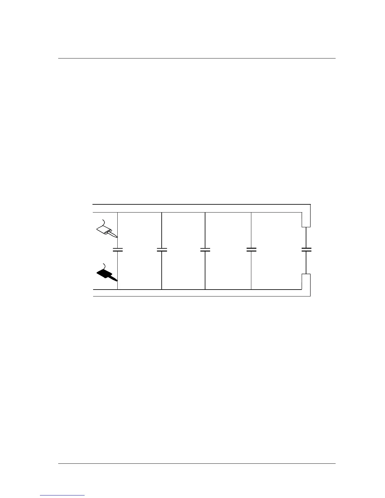
Figure 4-9 provides an example.
A
B
C
D
C2
C1
Vcc
GND
DRIVE SOURCE
C3 C4 C5
Figure 4-9 Isolation of Open Circuit Decoupling Capacitor
As the Drive Source is AC in TRACE, each capacitor conducts some current.
The Trace Probe can be used to identify the current flow. The display reading and tone give an indication
of its relative magnitude.
The reading at A would be the highest (the sum of four capacitor currents). The readings at B, C and D
would progressively diminish. The reading at D would be the lowest (only C5's current).
If C3 were open circuit, the readings at B and C would be equal. This method is most suitable for
capacitors in the range 0.1uF to 1.0uF.
Artisan Technology Group - Quality Instrumentation ... Guaranteed | (888) 88-SOURCE | www.artisantg.com